7-8
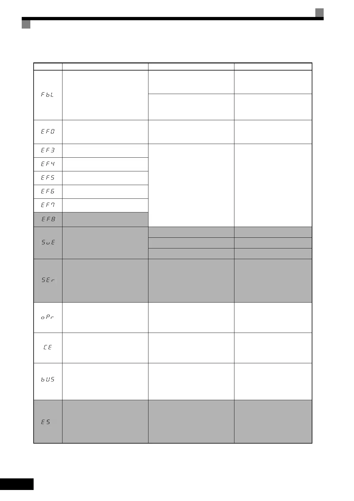
PID Feedback Reference Lost
A PID feedback reference loss was
detected (b5-12 = 2) and the PID feed-
back input was less than b5-13 (PID
feedback loss detection level) for
longer than the time set in b5-14 (PID
feedback loss detection time).
The settings in b5-13 and b5-14 aren’t
appropriate.
Check the settings in b5-13 and
b5-14.
The wiring of the PID feedback circuit
is incorrect.
Fix the wiring.
External Fault input from Commu-
nications Option Board
-
Check the Communications
Option Board and communica-
tions signals.
External Fault (Input Terminal S3)
An "external fault" was input from a
multi-function input terminal (S3 to
S8).
• Reset external fault inputs to the
multi-function inputs.
• Remove the cause of the exter-
nal fault.
External Fault (Input Terminal S4)
External Fault (Input Terminal S5)
External Fault (Input Terminal S6)
External Fault (Input Terminal S7)
External Fault (Input Terminal S8)
Zero-Servo Fault
The rotation position moved during
zero-servo operation.
The torque limit is too small. Increase the limit.
The load torque is too large. Reduce the load torque.
- Check for signal noise.
Exceeded Allowable Number of
Speed Search Retrials
The speed search has been retried
more than the number of times set in
b3-19 (Number of speed search retri-
als).
The settings in b3-17 and b3-18 aren’t
appropriate.
Make sure that the settings in b3-
17 and b3-18 are appropriate.
Digital Operator Connection Fault
The connection to the Digital Operator
was broken during operation for a Run
Command from the Digital Operator.
-
Check the connection to the Digi-
tal Operator.
MEMOBUS Communications Error
A normal reception was not possible
for 2 s or longer after control data was
received once.
-
Check the communications
devices and communications sig-
nals.
Option Communications Error
A communications error was detected
during a Run Command or while set-
ting a frequency reference from a
Communications Option Board.
-
Check the communications
devices and communications sig-
nals.
SI-T Watchdog Error
Consistency error of received control
data
Synchronization error between master
controller and Inverter for control
data.
Check the communications tim-
ing such as communications cycle.
Refer to MECHATROLINK COM-
MUNICATIONS INTERFACE
CARD INSTRUCTIONS
(TOBPC73060008) for details.
Table 7.1 Fault Displays and Processing (Continued)
Display Meaning Probable Causes Corrective Actions

 Loading...