July 2005 Preface Addition:
Safety Precautions
Maintenance and Inspection
y
Precaution about using an Inverter with an elevator
y
Precaution about times when a holding brake is necessary
Chapter 2
Revision:
IMPORTANT
2 in Connection Diagram
Addition: y
IMPORTANT 13 in Connection Diagram
y
IMPORTANT in Standard Connection Diagrams
Chapter 5 Revision: Note *2 about E2-01
Addition: y
L8-32
y
36 and 3D settings of multi-function output terminal
y
Note *7 about C4-02 in the table in Factory Settings that Change with the Control
Method (A1-01)
Chapter 6
Revision: y
Fig.6.49 Baseblock Commands
y
Fig.6.63 PID Control Block
y
Examples of torque-limit operation in Torque Control
y
Application Precautions in Copying Constants
y
Fig.6.81 Brake ON/OFF Sequence Circuit Configuration
y
Confirming Startup Current and Reducing Carrier Frequency in Using Inverters for
Elevating Machines
Addition: y
Information on frequency detection 5 in Using Frequency Detection
y
Operation Selection After Cooling Fan Fault
y
Description about the changes in the OV and BTR levels that depend on the input
voltage in Setting the V/f Pattern
y
Description about frequency detection 5, which is an Inverter output signal to engage a
holding brake, in Using Inverters for Elevating Machines
Chapter 7
Addition: y
Fault and Alarm Detections
Descriptions of FAN
y
Probable causes and corrective actions for the OC, GF, OH (OH1), OL1, OL2, CPF04,
and CPF05 faults as well as the OH alarm
Descriptions about a short-circuit between, the +V, -V, and AC terminals.
y
Note in Table 7.3 Operation Error Displays and Incorrect Settings
Revision: Probable causes and corrective actions for the CPF23 fault
Chapter 8
Addition: y
Descriptions in Periodic Maintenance of Parts
y
Description of how to attach the fan cover for 200 V Class Inverters of 22 kW or 30
kW and 400 V Class Inverters of 22 kW to 55 kW
y
Description of how to replace the cooing fan and
circ
ulation fan for 400 V Class
Inverters of 185 kW, 220 kW, and 300 kW
Chapter 10 Addition: Note *4 in Fig.10.9
March 2006 Preface Addition: Safety Precautions
Trial Operation
Inverter settings precautions
Chapter 1 Revision: Table 1.9 Removing the Terminal Cover (Model CIMR-F7A20P4 Shown Above)
Chapter 2
Addition: y
Note in Table 2.4 Main Circuit Terminal Functions
y
IMPORTANT 14 and 15 in Connection Diagram
Revision: Description of installing a ground fault interrupter in Wiring the Main Circuits
Chapter 4 Revision: Description of stationary autotuning 2
Chapter 5
Addition: y
Following constants
H5-10, o2-09
y
Note in the table of L2 constants
Revision: Note *3 about E2-03 and E4-03
Chapter 6
Addition: y
Inputting Master Speed Frequency Reference Only (Current Input) in Frequency Refer-
ence
y
Following items in Continuing Operation
y
IMPORTANT in Speed Search
y
Additional description of master speed analog input in Continuing Operation at
Constant Speed When Frequency Reference Is Lost
Revision: y
Restarting Operation After Transient Fault (Auto Restart Function) in Continuing
Operation
y
Torque Control in Individual Operation
Example Diagrams of winding and rewinding operation during torque control
Chapter 7
Addition: y
Table 7.2 Causes and Corrective Actions for When the Digital Operator Goes Dark
y
The Inverter does not operate in Troubleshooting
Revision: Probable causes and corrective actions for the OC, GF, PUF, OV, UV1, UV2, UV3,
OH (OH1), OL1, OL2, and CPF03 to CPF05 faults and OH, PGO, and DEV alarms
Chapter 9 Addition: Notes *8 and *9 in Table 9.3
Chapter 10 Revision: Table 10.5 EMC Noise Filters
December 2007 Back cover Revision: Address
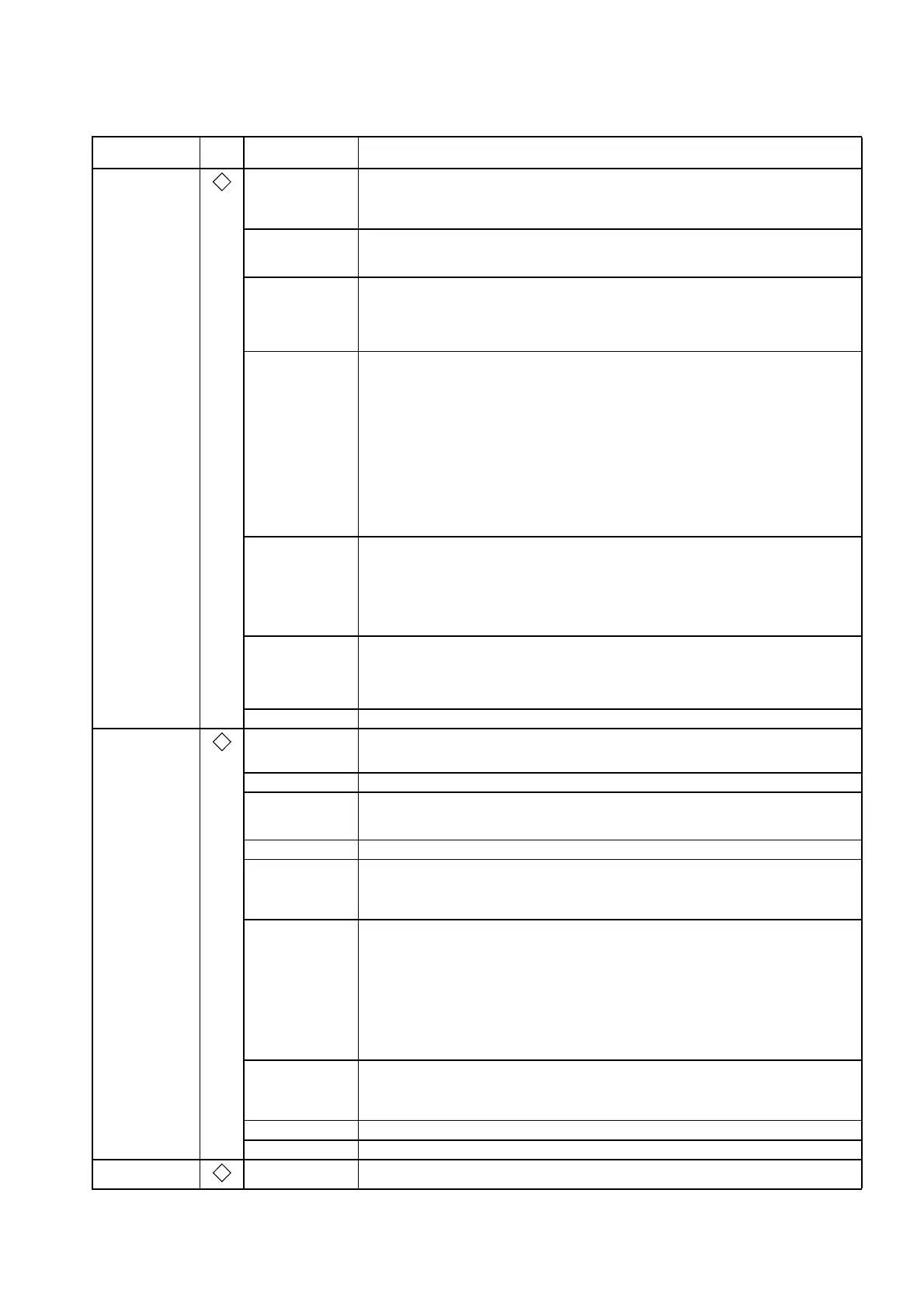
Date of
Publication
Rev.
No.
Section Revised Content

 Loading...


