3 WIRING
23
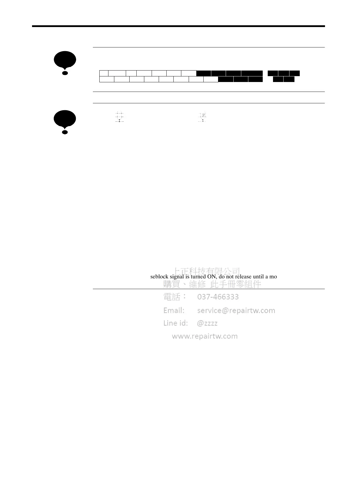
Layout of control circuit terminals
21 22 23 9 10
25 26 27 33 18 19 2011 12(G)
123 4567 8
13 14 15 16 17
1.
indicates shielded wires and indicates twisted-pair shielded wires.
2. Either control circuit terminal 13 or 14 can be used. (For simultaneous inputs, the two
signals are added internally.)
3. Control circuit terminal 15/33 of +15 V/-15 V has a maximum output current capacity of
20 mA.
4. Multi-function analog output should be used for monitoring meters (e.g. output frequency
meter) and should not be used for feedback control system. Use analog monitor cards
(Model AO-12) for the control system, for a more accurate signal.
5. When using a braking resistor unit, set the constant L3-01 to “0” (overvoltage prevention
level is “disabled”). If it is not changed, the motor may not stop within the set decel time.
6. When using model ERF braking resistor (inverter-mounted type), set the constant L8-01
to “01” (braking resistor protection selection to “enabled”). If it is not changed, the brak-
ing resistor cannot be protected.
7. When installing a DC reactor (optional for models of 15kW or below), remove the short-
circuit bar between ¨1 and ¨2 terminals and connect a DC reactor with the terminals.
8. The models of 200V 30 to 75kW or 400V 55 to 160kW cannot be connected with DC pow-
er supply.
9. Once external baseblock signal is turned ON, do not release until a motor stops.
NOTE
NOTE
 Loading...