3 WIRING
37
(2) Precautions on Control Circuit Wiring
S Separate control circuit wires 1 to 33 from main circuit wires R, S, T, B1, B2, U, V,
W,
©
,
¨
1,
¨
2,
¨
3 and other power cables to prevent erroneous operation caused by
noise interference.
S Separate the wiring of control circuit terminals 9, 10, 18, 19 and 20 (contact output)
from those of terminals 1 to 8, 21, 22, 23, 25, 26, 27, 33 and 11 to 17.
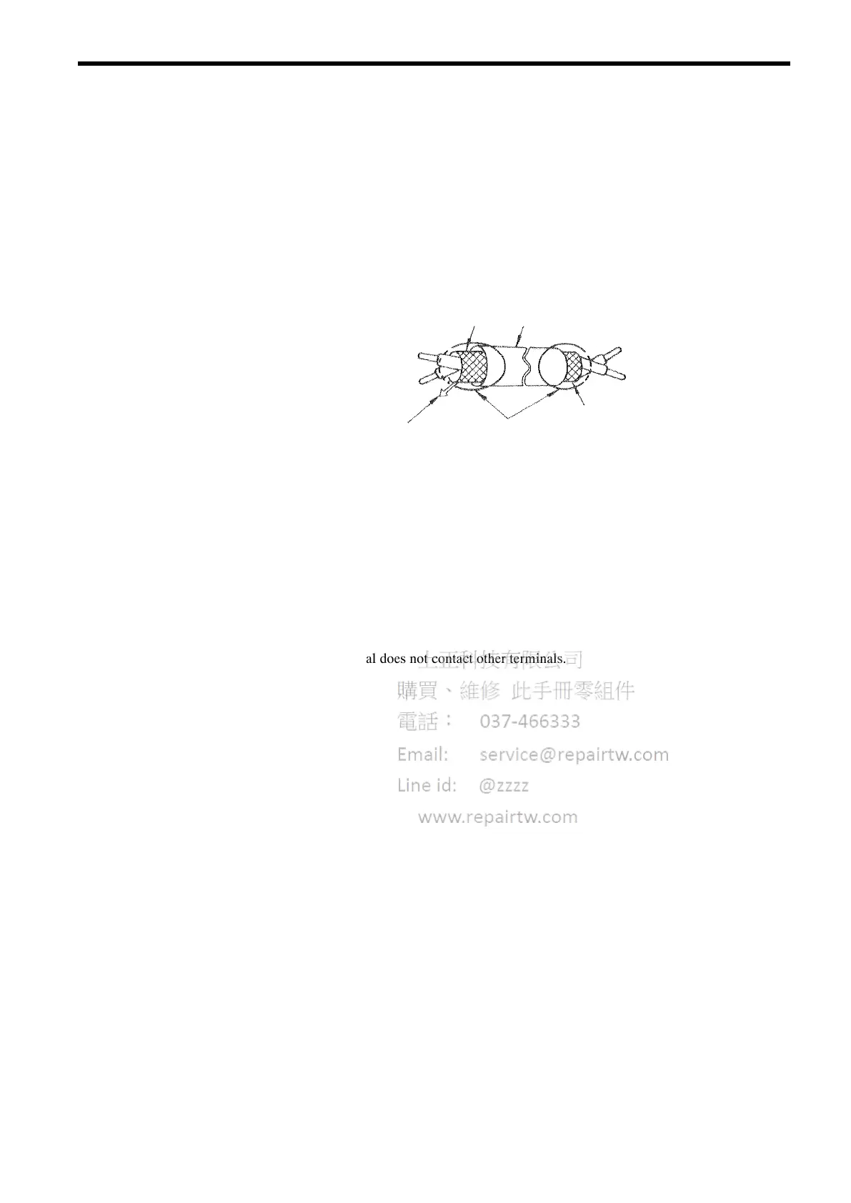
S Use twisted shielded or twisted-pair shielded wire for the control circuit line and con-
nect the shield sheath to the inverter terminal 12. See Fig. 17. Wiring distance should
be less than 50 m.
To inverter shield
sheath terminal 12
Shield Sheath Armor
Insulate these parts
with insulating tape.
Never connect.
Fig. 17 Shielded Wire Termination
3.5 WIRING INSPECTION
After completing of installation and wiring, check for the following items. Never use control circuit
buzzer check.
V Wiring is proper.
V Wire clippings or screws are not left in the unit.
V Screws are securely tightened.
V Bare wire in the terminal does not contact other terminals.
 Loading...