84
APPENDIX 4 CONSTANTS LIST
The numbers of constants displayed in the digital operator depend on the setting of constant access
level (A1-01). For details, refer to Descirptive Manual for Constants.
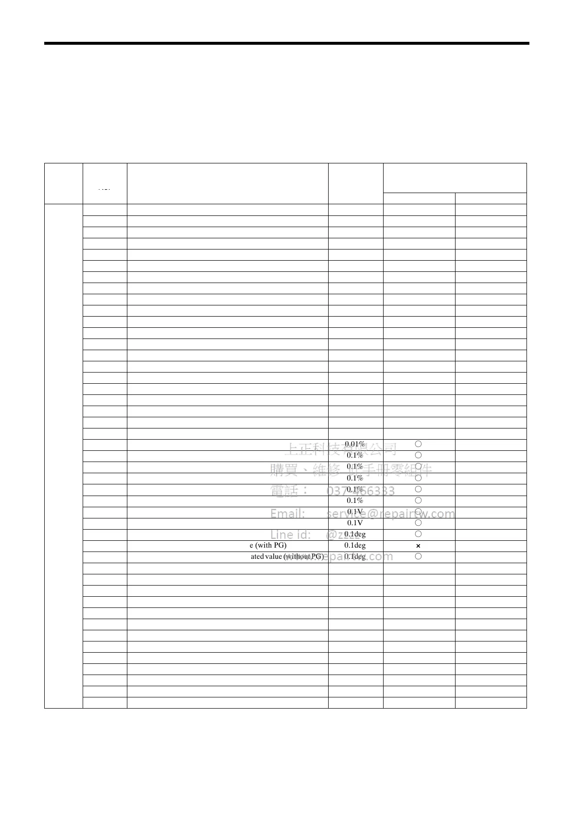
Table A−4 Monitor Item List
Constant
No.
Name Unit
Control Method
(f = Monitor enabled,
× = Monitor disabled)
*1
Open loop vector Flux vector
U1-01 Speed reference 0.01%
*2
f f
U1-02 Output frequency 0.01Hz
f f
U1-03 Output current 0.1A
*3
f f
U1-04 Control method [No.]
f f
U1-05 Motor speed 0.01%
*2
f f
U1-06 Output voltage reference 0.1V
f f
U1-07 DC bus voltage 1V
f f
U1-08 Output power 0.1kW
f f
U1-09 Torque reference (internal) 0.1%
f f
U1-10 Input terminal status [Bit]
f f
U1-11 Output terminal status [Bit]
f f
U1-12 Operation status [Bit]
f f
U1-13 Cumulative operation time 1H
f f
U1-14 Software No. (at FLASH side) [No.]
f f
U1-15 Control circuit terminal 13 input voltage 0.1%
f f
U1-16 Control circuit terminal 14 input current/voltage 0.1%
f f
U1-17 Control circuit terminal 16 input voltage 0.1%
f f
U1-18 Motor q-axis current (Iq) 0.1%
f f
U1-19 Motor d-axis current (Id) 0.1%
f f
U1-20 Speed reference after soft-start 0.01%
*2
f f
U1-21 ASR input (speed deviation) 0.01%
f f
U1-22 ASR output 0.01%
f f
Monitor U1-27 q-axis current reference 0.1%
f f
U1-28 d-axis current reference 0.1%
f f
U1-29 Voltage limit control output 0.1%
f f
U1-30 q-axis current control output 0.1%
f f
U1-31 d-axis current control output 0.1%
f f
U1-32 Output voltage reference Vq 0.1V
f f
U1-33 Output voltage reference Vd 0.1V
f f
U1-36 Output voltage phase 0.1deg
f f
U1-37 Magnetic-pole position detection value (with PG) 0.1deg
×
f
U1-38 Magnetic-pole position detection estimated value (without PG) 0.1deg
f
×
U1-41 LED check (diagnosis)
f f
U1-42 Operation status 2 [Bit]
f f
U1-43 Command 1 from transmission option [Bit]
f f
U1-44 Command 2 from transmission option [Bit]
f f
U1-45 External torque reference 0.01%
f f
U1-46 Torque compensation 0.01%
×
f
U1-47 DO-08/H output status [Bit]
f f
U1-48 Momentary power loss drop amount 0.01%
f f
U1-49 Software No. (at CPU side) [No.]
f f
U1-50 Speed detection PG counter value Pulse
×
f
U1-51 Output current phase 0.1deg
f f
U1-53 PID feedback amount 0.01%
f f
U1-54 DI-16H input status [BCD]
f f
*1 Even if f is indicated, some constants are not displayed depending on access level.
*2 The unit varies depending on the setting of o1-03.
*3 0.01A for models of 7.5 kW or below.
 Loading...