7 TROUBLESHOOTING
67
7 TROUBLESHOOTING
This chapter describes the inverter fault display and the fault contents caused by motor/machine mal-
functions and the corrective actions to be taken.
7.1 FAULT DIAGNOSIS AND CORRECTIVE ACTIONS
When the VS-686SS5 detects a fault, the fault is displayed on the digital operator and activates the fault
contact output and the motor coasts to a stop. Check the cause in Table 31 and take the corrective
actions. If the inspections or corrective actions described cannot solve the problem, contact your
YASKAWA representative immediately.
To restart, turn ON the reset input signal or depress [>RESET] key or shut OFF the main circuit power
supply once, to reset the stop status.
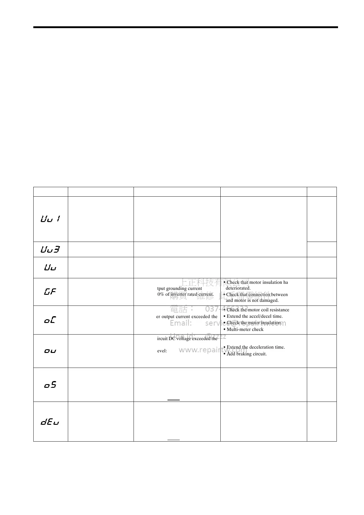
Table 31 Fault Diagnosis and Corrective Actions
Fault Display Description Details Corrective Action Rank*
Main circuit undervoltage
(UV1)
The main circuit DC voltage fell below
the undervoltage detection level while
running or decelerating and momentary
power loss ride-through time elapsed.
Detection level:
200 V class: Approx. 19 0 V or less
400 V class: Approx. 38 0 V or less
• Check the power supply wiring.
• Correct the line voltage.
A
Pre-charge contactor open
(UV3)
The pre-charge contactor opened while
running or decelerating.
A
• The main circuit DC voltage fell below
Momentary power
oss
UV
t
eun
ervo
tage
etect
on
eve
.
• The pre-charge contactor opened.
Ground fault (GF)
Inverter output grounding current
exceeded 50% of inverter rated current.
• Check that motor insulation has not
deteriorated.
• Check that connection between inverter
and motor is not damaged.
A
Overcurrent (OC)
The inverter output current exceeded the
OC level.
• Check the motor coil resistance.
• Extend the accel/decel time.
• Check the motor insulation.
• Multi-meter check
A
Overvoltage (OV)
The main circuit DC voltage exceeded the
OV level.
Detection level:
200 V class: Approx. 406 V
400 V class: Approx. 812 V
• Extend the deceleration time.
• Add braking circuit.
A
(C during
stop)
Overspeed (OS)
The motor speed exceeded the overspeed
level (F1-08).
Detection time: F1-09
The inverter operates according to the set-
ting of constant F1-03
.
Check the load. B
Speed deviation (dEV)
The deviation of the speed reference and
speed feedback exceeded the regulation
level (F1-10).
Detection time: F1-11
The inverter operates according to the set-
ting of constant F1-04
.
Check the load. B
(Cont’d)
 Loading...