72
APPENDIX 1 SPECIFICATIONS
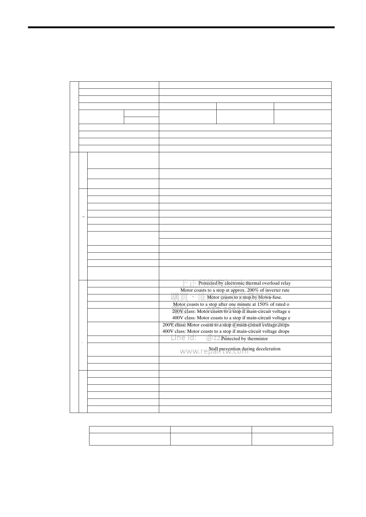
Table A−1 Variable Torque Series Specifications
Model SSR1-
Mounting Method Foot-mounted type, flange-mounted type
Enclosure Totally-enclosed fan-cooled type (IP44)
r
Rated min
-1
1750 min
-1
1450 min
-1
1150 min
-1
otor
200V class
M
utput Range
400V class
.
to 7
W
.
to
W
.
to
W
Speed Control Range (Continuous) 1:10 (Variable torque) (Refer to * for constant output range.)
Time Rating Continuous
Insulation Class Class F
Sensor Without PG
upply
Input Voltage
200V class: 200/208/220V 50Hz, 200/208/220/230V 60Hz
400V class: 400/415/440/460V 50/60Hz
er S
Allowable Voltage Fluctuation +10% to -15%
Po
Allowable Frequency Fluctuation
± 5%
Control Method Open loop vector
Starting Torque 50%
Speed Control Range 1:10
tics
Speed Control Accuracy
± 0.2%
rist
Torque Limit Provided
cte
Torque Accuracy
± 10%
har
Digital command: 0.01%
lC
Run
pee
Reso
ut
on
Analog command: 0.05% (11 bit + code)
trol
Overload Capacity 150% of rated output current for one minute
Con
Run Speed Setting Signal -10 to 10V, 0 to 10V, 4 to 20mA
Accel/decel Time 0 to 6000 seconds
ter
Main Functions
PID control, overtorque detection, torpue limit, multi-step speed operation,
accel/decel time change, 3-wire sequence, auto-tuning
vert
Motor Overload Protection Protected by electronic thermal overload relay
In
Instantaneous Overcurrent Motor coasts to a stop at approx. 200% of inverter rated current.
Blown Fuse Protection Motor coasts to a stop by blown-fuse.
ns
Overload Motor coasts to a stop after one minute at 150% of rated output current.
unctio
Overvoltage
200V class: Motor coasts to a stop if main-circuit voltage exceeds 406V.
400V class: Motor coasts to a stop if main-circuit voltage exceeds 812V.
ctive F
Undervoltage
200V class: Motor coasts to a stop if main-circuit voltage drops to 190V or below.
400V class: Motor coasts to a stop if main-circuit voltage drops to 380V or below.
ote
Heatsink Overheat Protected by thermistor
Pr
Stall Prevention
(Overvoltage Prevention)
Stall prevention during deceleration
Ground Fault Protected by electronic circuit
Power Charge Indication Charge LED stays ON until bus voltage drops below 50V.
Location Indoor (protected from corrosive gases and dust)
ent
Humidity 90% RH or less (non-condensing)
nm
Storage Temperature -20°C to +60°C
iro
Ambient Temperature -10°C to +40°C (Enclosed wall-mounted type), -10°C to +45°C (Open chassis type)
Env
Elevation 1000 m or less
Vibration 9.8 m/s
2
(1G) at 10 to less than 20 Hz, up to 2 m/s
2
(0.2G) at 20 to 50 Hz
*Constant output range is as follows:
1750 min
-1
1450 min
-1
1150 min
-1
1:1.5 (0.4 to 75 kW)
1:1.3 (90 to 160 kW)
1:1.5 (0.4 to 55 kW)
1:1.3 (75 to 160 kW)
1:1.5 (0.4 to 45 kW)
1:1.3 (55 to 160 kW)
Note: Variable torque series cannot be used to the following applications:
• Commercial power supply / inverter power supply switch operation
• One inverter drives several motors (multi-motor drive).
• Start during motor run
 Loading...