13 European Standards
YASKAWA TOEPC7106171FD FP605 DRIVE INSTALLATION & PRIMARY OPERATION 97
Type of Grounding Diagram
Single-phase, grounded at the end point
Three-phase variable transformer without solidly grounded neutral
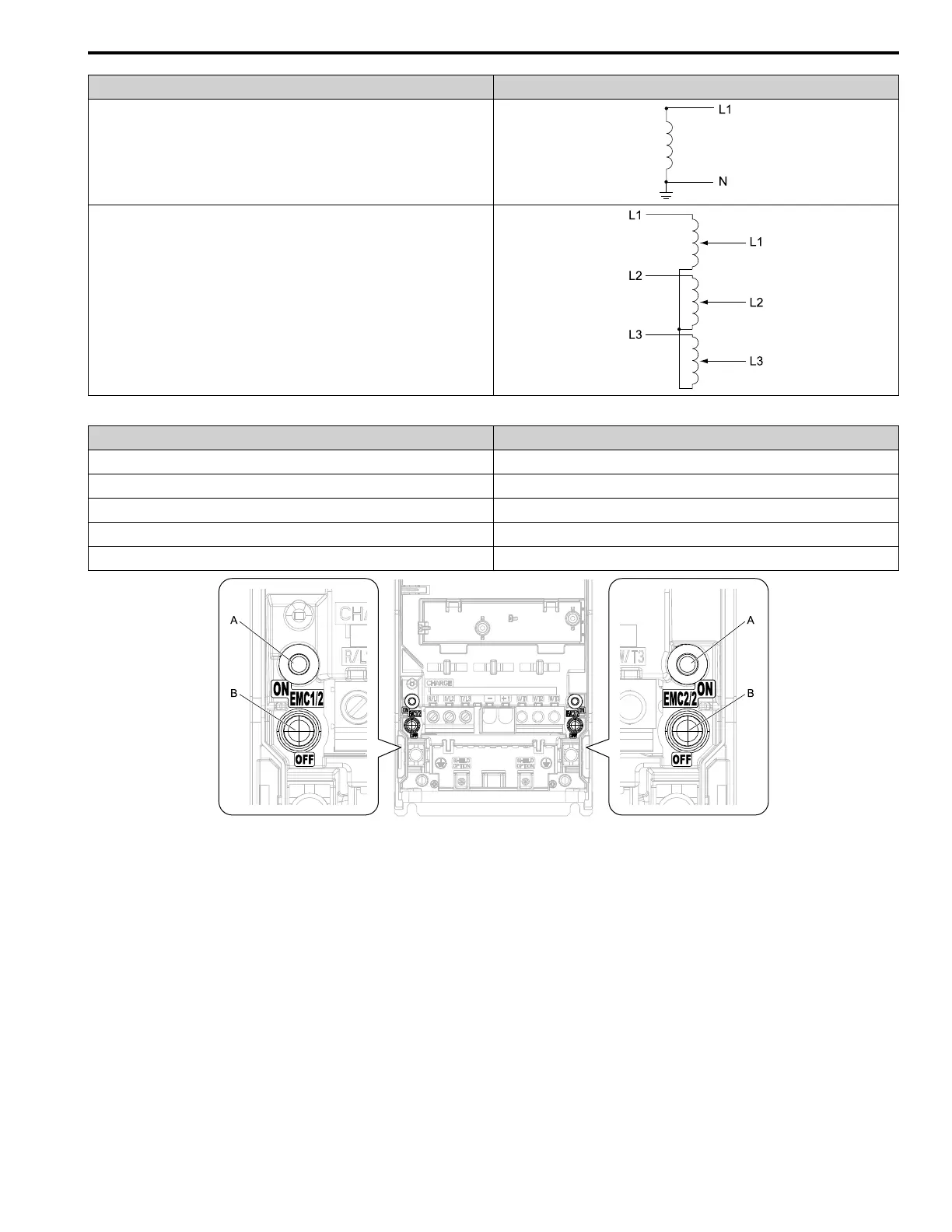
Table 13.7 EMC Filter Switch Location
Model Switch Location Diagram
2011, 2017, 4005 - 4014 Figure 13.7
2024, 2031, 4021 - 4034 Figure 13.8
2046, 2059, 4040 - 4065 Figure 13.9
2075 - 2114, 4077 - 4124 Figure 13.10
2143, 2169, 4156 Figure 13.11
A - SW (ON) B - Screw (OFF)
Note:
To comply with IEC61800-3 on drive models 2xxxA and 4xxxA with no built-in EMC filter, turn on the EMC filter switch on the left side.
Figure 13.7 EMC Filter Switch Location 1