32 YASKAWA ELECTRIC EZZ010926 FSDrive-MV1000 Instructions
1.4 Component Names and Configuration
1.4 Component Names and Configuration
This section covers the names and configuration of the drive components.
The external appearance of the drive and the layout of the internal devices are shown in the figures below.
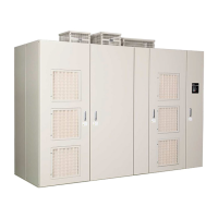
Figure 1. 7
Figure 1.7 External Appearance, Viewing Doors (Drive: 2-kV Class, 600 HP)
Figure 1. 8
Figure 1.8 Internal Layout (Drive: 2-kV Class, 600 HP)
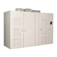
Figure 1. 9
Figure 1.9 External Appearance, Viewing Doors (Drive: 3-kV Class, 800 kVA)
A – Digital Operator
A – Cooling fan D – Main circuit output terminals
B – Power Cell E – Main circuit input terminals
C – Control circuit terminal
A – Digital Operator
E
A
B
C
D
Transformer
panel
Power Cell panel
Control
panel
%$
%$
%$
%$
ᵈᗧ
%#76+10
ᵈᗧ
%#76+10
ᵈᗧߊߛߐޕ
2NGCUGFQPQVECVEJVJGHKPIGT
DGVYGGPRCPGNHNCOGCPFVJKUWPKV
ޓࡄࡀ࡞ࡈ㧙ࡓߣᧄ࡙࠾࠶࠻ߣߩ㑆ߢᜰࠍ߹ߥࠃ߁ߦ
ޓャㅍᤨߩࡂࡦ࠼࡞ᛮߌ㒐ᱛ↪ߦࡄࡀ࡞ࡈ㧙ࡓⓣߣࡂࡦ࠼࡞
ߩ㑆ߦ⚿᧤ࡃࡦ࠼╬ࠍᏎ߈ઃߌߡߐޕ
2NGCUGFQPQVECVEJVJGHKPIGT
DGVYGGPRCPGNHNCOGCPFVJKUWPKV
㧭㧝 㧭㧞 㧮㧝 㧮㧞 㧯㧝 㧯㧞
'&
$0.
$0.
5%
4%
'&
'&
'&
'&
'&
'&
'&
'&
'&
'&
.
.
.
.
.
.
.
.
.
$0.
Transformer panel
Power Cell panel
Control panel
A

 Loading...


