1.4 Component Names and Configuration
YASKAWA ELECTRIC EZZ010926 FSDrive-MV1000 Instructions 35
Figure 1.16
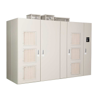
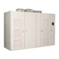
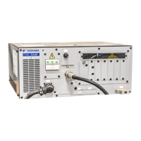
Figure 1.16 Internal Layout (Drive: 11-kV Class, 2650 kVA)
The drive is composed of the following three elements.
• Transformer panel
• Power Cell panel
• Control panel
Note: A digital operator including the functions of parameter writing/reading and status/fault monitoring, and a connector (USB) for
DriveWizard Plus MV communications are provided on the control panel door. For details on the names and functions of each
part of the digital operator controls, see Using the Digital Operator on page 107.
A – Cooling fan D – Main circuit output terminals
B – Power Cell E – Main circuit input terminals
C – Control circuit terminal
A
E
B
C
D
ࠕ
ࠗ
%$%$
%$%$ %$%$
%$%$
ᵈᗧᵈᗧ
%#76+10%#76+10
ᵈᗧᵈᗧ
%#76+10%#76+10
ᵈᗧᵈᗧ
%#76+10%#76+10
ᵈᗧᵈᗧ
%#76+10%#76+10
ᵈᗧᵈᗧ
%#76+10%#76+10
ᵈᗧᵈᗧ
%#76+10%#76+10
'&'&
5%5%
4%4%
'&'&
'&'&
'&'&
'&'&
'&'&
'&'&
'&'&
'&'&
'&'&
'&'&
..
..
..
..
..
..
..
..
..
࠰࠰
ࠕࠕ
࠻࠻
࠻࠻
࠻࠻
࠻࠻
࠻࠻
࠻࠻
࠻࠻
ࡕࡕ
ࠈࠈ
࠰࠰
Transformer panel Power Cell
panel
Control panel

 Loading...


