Figure i.19 Terminal A2 Set to Current Input; A1 and A3 Set to Voltage Input
Table i.14 Jumper S1 Settings
Setting Description
V (top position) Voltage input (-10 to +10 V or 0 to 10 V)
I (bottom position) Current input (4 to 20 mA or 0 to 20 mA)
Table i.15 Voltage/Current Selection Parameter Details
No. Parameter Name Description
Setting
Range
Default
Setting
H3-01 Terminal A1 signal level selection
Selects the signal level for terminal A1.
0: 0 to 10 Vdc
1: 0 to 10 Vdc Bipolar
2: 4 to 20 mA
3: 0 to 20 mA
0 to 3 0
H3-05 Terminal A3 signal level selection
Selects the signal level for terminal A3.
0: 0 to 10 Vdc
1: 0 to 10 Vdc Bipolar
2: 4 to 20 mA
3: 0 to 20 mA
0 to 3 0
H3-09 Terminal A2 signal level selection
Selects the signal level for terminal A2.
0: 0 to 10 Vdc
1: 0 to 10 Vdc Bipolar
2: 4 to 20 mA
3: 0 to 20 mA
0 to 3 2
n
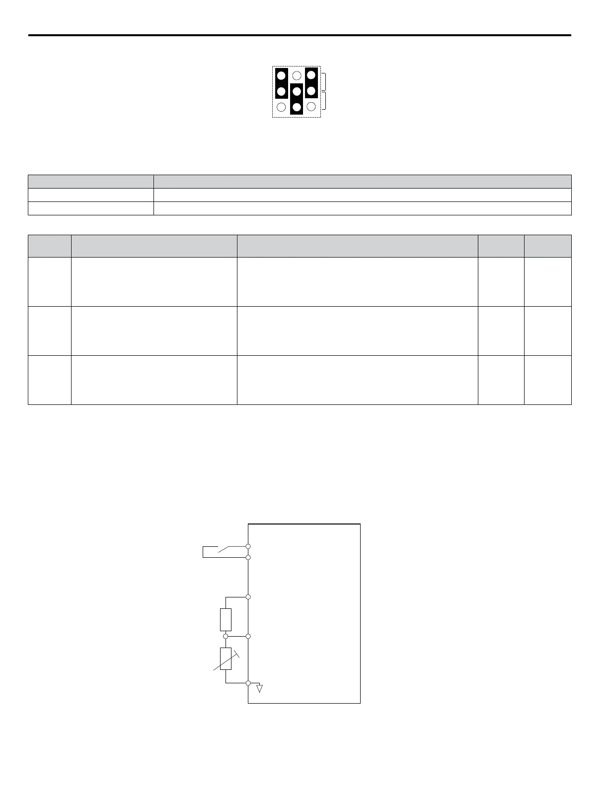
Motor Protection Using a Positive Temperature Coefficient (PTC) Thermistor
Connect a motor PTC can to an analog input of the drive for motor overheat protection.
The motor overheat alarm level triggers an oH3 alarm and the drive continues the operation selected in L1-03. The overheat
fault level triggers an oH4 fault, outputs a fault signal, and the drive stops the motor using the stop method selected in L1-04.
Connect the PTC between terminals AC and A3 and install a 12 kOhm resistor between terminals V+ and A3 as shown in
Figure i.20. Set H3-05 to 0 and H3-06 to E.
Note: A 12 kOhm resistor must be connected between one of the terminals A1, A2, or A3 and V+ for PTC functionality. Connect the 12 kOhm
resistor to the same terminal as the PTC input. Do not connect terminals V+ to AC, or damage to the drive may result.
P1000 Drive
Multi-function input
PTC
thermistor
A3 (0-10 V)
AC
V+ Power supply
+10.5 Vdc,
max. 20 mA
12 kOhm
resistor
PTC external circuit
(customer supplied)
Figure i.20 Connection of a Motor PTC
i.3 Electrical Installation Safety
42
YASKAWA ELECTRIC TOEP YAIP1U 03B YASKAWA AC Drive – P1000 Safety Precautions

 Loading...


