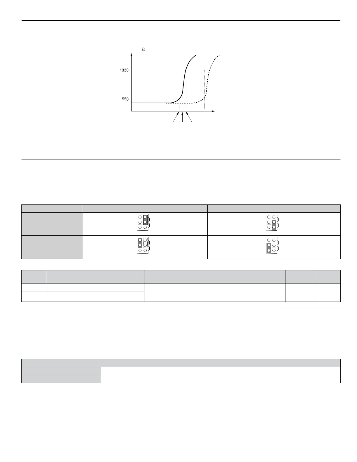
The PTC must exhibit the characteristics shown in Figure i.21 in one motor phase. The motor overload protection of the drive
expects 3 of these PTCs to be connected in a series.
Resistance ( )
Class F
150 ºC
Class H
180 ºC
Tr: threshold value
Temperature
Tr’
Tr + 5K (oH4 Fault Level)TrTr - 5K (oH3 Alarm Level)
Figure i.21 Motor PTC Characteristics
Set up overheat detection using a PTC using parameters L1-03, L1-04, and L1-05 as explained in the following sections.
u
Terminal AM/FM Signal Selection
The signal type for terminals AM and FM can be set to either voltage or current output using jumper S5 on the terminal board
as explained in Table i.16. When changing the setting of jumper S5, parameters H4-07 and H4-08 must be set accordingly.
The default selection is voltage output for both terminals.
Table i.16 Jumper S5 Settings
Terminal Voltage Output Current Output
Terminal AM
AMFM
V
I
AMFM
V
I
Terminal FM
AMFM
V
I
AMFM
V
I
Table i.17 Parameter H4-07 and H4-08 Details
No. Parameter Name Description
Setting
Range
Default
Setting
H4-07 Terminal AM signal level selection 0: 0 to 10 Vdc
1: -10 to 10 Vdc
2: 4 to 20 mA
0 to 2 0
H4-08 Terminal FM signal level selection
u
MEMOBUS/Modbus Termination
This drive is equipped with a built-in termination resistor for the RS-422/485 communication port. DIP switch S2 enables or
disabled the termination resistor as shown in Table i.18. The OFF position is the default. The termination resistor should be
placed to the ON position when the drive is the last in a series of slave drives. Refer to Switches and Jumpers on the Terminal
Board on page 40 to locate switch S2.
Table i.18 MEMOBUS/Modbus Switch Settings
S2 Position Description
ON Internal termination resistor ON
OFF Internal termination resistor OFF (default setting)
i.3 Electrical Installation Safety
YASKAWA ELECTRIC TOEP YAIP1U 03B YASKAWA AC Drive – P1000 Safety Precautions
43

 Loading...


