6 Related Parameters
YASKAWA ELECTRIC TOBP C730600 75B YASKAWA AC Drive Option PG-B3 Installation Manual 37
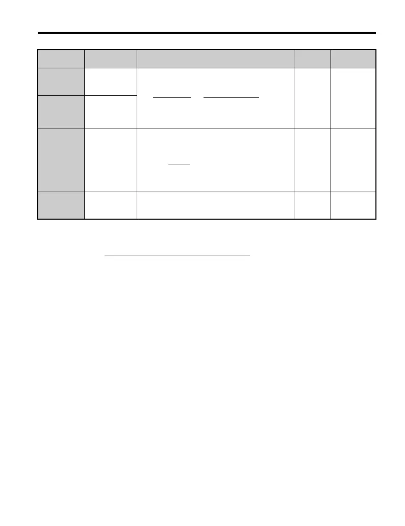
F1-33
(3B2)
<5> <7>
PG 2 Gear Teeth
1
Sets the number of gear teeth between the PG and
motor.
A gear ratio of 1 will be used if any of these
parameters is set to 0.
V/f w/ PG
Default: 0
Min: 0
Max: 1000
F1-34
(3B3)
<5> <7>
PG 2 Gear Teeth
2
F1-35
(3BE)
<7>
PG 2 Division
Rate for Pulse
Mon
Sets the division ratio for PG encoder pulse output.
Set as a three-digit number where x is the first digit, y
is the second digit, and z is the third digit:
When only the A pulse is read, this ratio is disabled
and pulses are set as 1/32 : 1.
V/f w/ PG
CLV
Default: 1
Min: 1
Max: 132
F1-37
(3BD)
<7>
PG 2 Signal
Selection
0: A pulse detection
1: AB pulse detection
V/f w/ PG
Default: 0
Range: 0, 1
<1> Varies by drive model.
<2> Use the following formula to calculate the number of output pulses for the PG encoder:
<3> Available only when using connector CN5-C.
<4> Dependent upon A1-02.
<5> Available only in V/f w/PG.
<6> A second PG encoder (PG 2) may not be possible depending on the drive series. Refer to the drive Technical
Manual for the drive in your application.
<7> Available only when using connector CN5-B.
No.
(Addr. Hex)
Name Description
Control
Method
Values
Pulses × 60
F1-31
×
F1-33 (load side)
F1-34 (motor side)
f
PG
(Hz)
Motor speed at maximum frequency output (min
-1
)
60
×
PG rating (p/rev)
=
TOBP_C730600_75B_1_0_E.book 37 ページ 2017年2月17日 金曜日 午後3時2分