8.3 Wiring Specifications
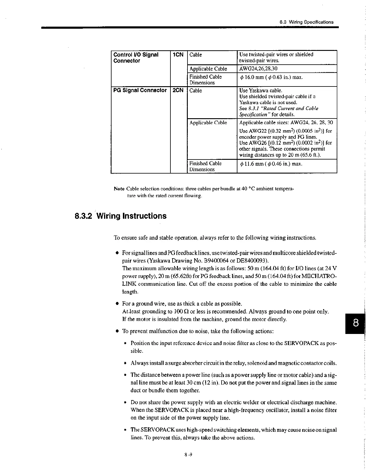
Control I/O Signal
Connector
1CN
Cable
Use twisted-pair wires or shielded
twisted-pair wires.
Applicable Cable
AWG24,26,28,30
Finished Cable
Dimensions
0 16.0 mm ( 0 0.63 in.) max.
PG Signal Connector
2CN
Cable Use Yaskawa cable.
Use shielded twisted-pair cable if a
Yask aw a cable is not used.
See 8.3.1 "Rated Current and Cable
Specification" for details.
Applicable Cable
Applicable cable sizes: AWG24, 26, 28, 30
Use AWG22 [(0.32 mm2) (0.0005 in2)] for
encoder power supply and FG lines.
Use AWG26 [(0.12 mm2) (0.0002 in2)] for
other signals. These connections permit
wiring distances up to 20 m (65.6 ft.).
Finished Cable
Dimensions
0 11.6 mm ( 0 0.46 in.) max.
Note Cable selection conditions: three cables per bundle at 40 °C ambient tempera-
ture with the rated current flowing.
8.3.2 Wiring Instructions
To ensure safe and stable operation, always refer to the following wiring instructions.
• For signal lines and PG feedback lines, use twisted-pair wires and multicore shielded twisted-
pair wires (Yaskawa Drawing No. B9400064 or DE8400093).
The maximum allowable wiring length is as follows: 50 m (164.04 ft) for I/0 lines (at 24 V
power supply), 20 m (65.62ft) for PG feedback lines, and 50 m (164.04 ft) for MECHATRO-
LINK communication line. Cut off the excess portion of the cable to minimize the cable
length.
• For a ground wire, use as thick a cable as possible.
At_least grounding to 100 SI or less is recommended. Always ground to one point only.
If the motor is insulated from the machine, ground the motor directly.
• To prevent malfunction due to noise, take the following actions:
• Position the input reference device and noise filter as close to the SERVOPACK as pos-
sible.
• Always install a surge absorber circuit in the relay, solenoid and magnetic contactor coils.
• The distance between a power line (such as a power supply line or motor cable) and a sig-
nal line must be at least 30 cm (12 in). Do not put the power and signal lines in the same
duct or bundle them together.
• Do not share the power supply with an electric welder or electrical discharge machine.
When the SERVOPACK is placed near a high-frequency oscillator, install a noise filter
on the input side of the power supply line.
• The SERVOPACK uses high-speed switching elements, which may cause noise on signal
lines. To prevent this, always take the above actions.
8 -9

 Loading...


