Configuration and Connections
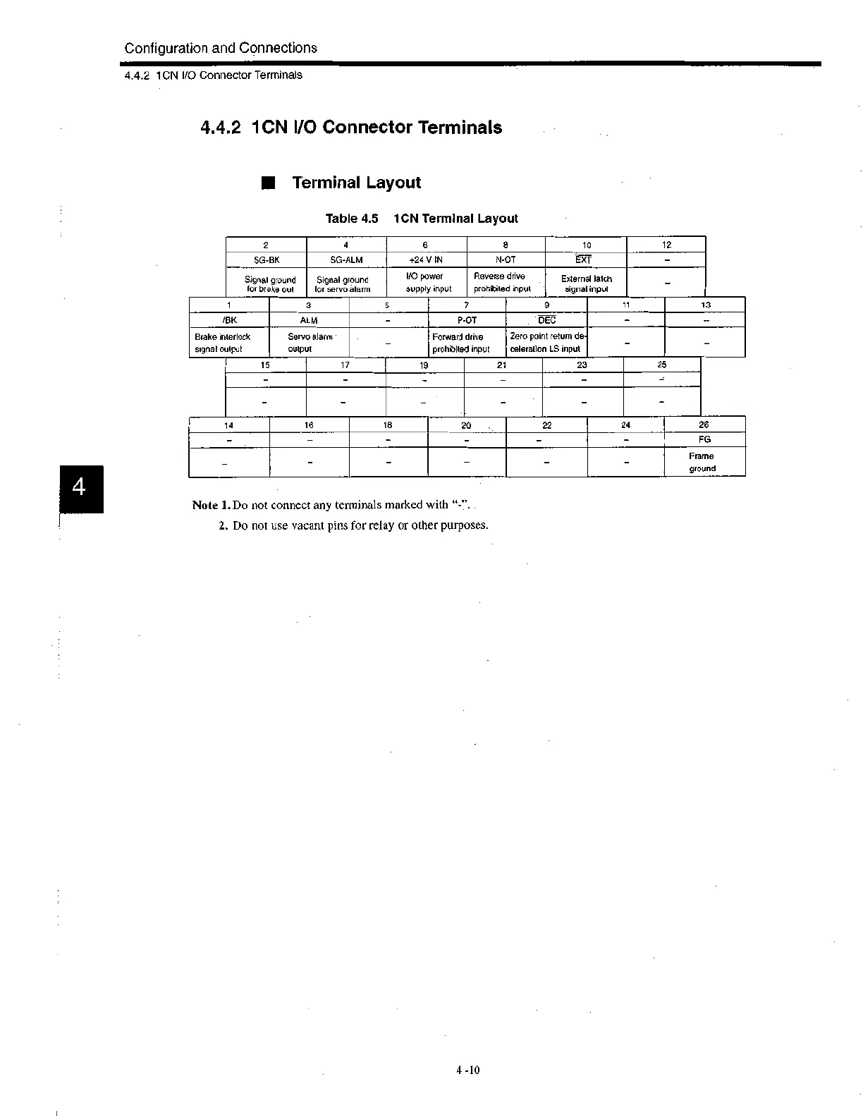
1
3 5
7 9
1
13
/BK
ALM —
P-OT DEC
—
—
Brake interlock
signal output
Servo alarm
output
Forward drive
prohibited input
Zero point return de-
celeration LS input
—
14
16 18
20 22
24
26
—
—
— — — — FG
_
—
_ Frame
ground
4.4.2 1CN I/O Connector Terminals
4.4.2 1CN I/O Connector Terminals
III Terminal Layout
Table 4.5 1CN Terminal Layout
2
4
6
8
10
12
SG-BK SG-ALM
+24 V IN N-OT EXT
Signal ground
for brake out
Signal ground
for servo alarm
I/O power
supply input
Reverse drive
prohibited input
External latch
signal input
15
17 19
21 23
25
Note 1. Do not connect any terminals marked with "-
2. Do not use vacant pins for relay or other purposes.
4 -10

 Loading...


