Servodrives Dimensional Drawings
A A Channel Output K —
B A Channel Output L —
C
B Channel Output M
—
D B Channel Output N —
E C Channel Output P —
F C Channel Output
R -
G 0 V S
—
H
+5 VDC T
-
J
FG (Frame Ground)
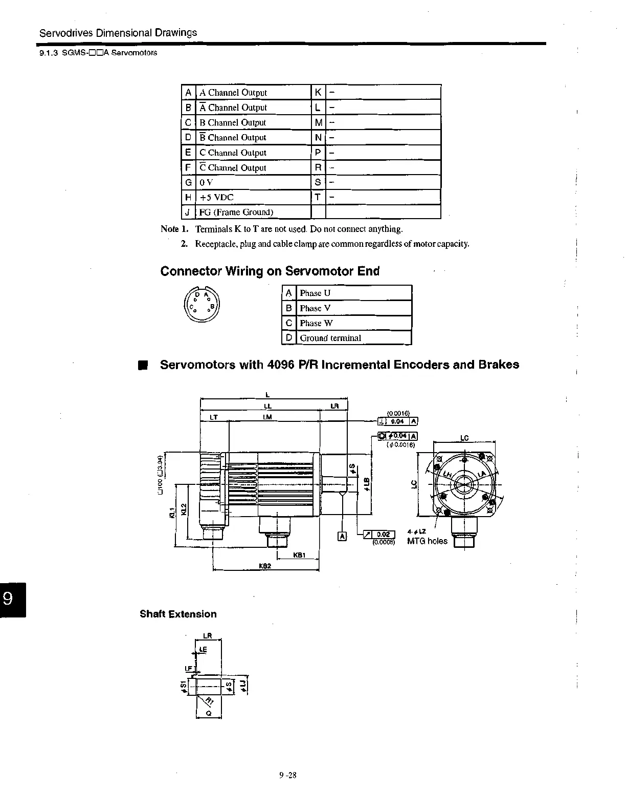
A
Phase U
B Phase V
C Phase W
D Ground terminal
9.1.3 SGMS-DEIA Servomotors
Note 1. Terminals K to T are not used. Do not connect anything.
2. Receptacle, plug and cable clamp are common regardless of motor capacity.
Connector Wiring on Servomotor End
• Servomotors with 4096 P/R Incremental Encoders and Brakes
L
LL LR
LT LM
(0.0016
11100 (113.94)
L KB1
K82
CO
—t
Shaft Extension
9
0.04
A
# 0.04 IA
( 0.0016)
-{," 0.02 4f L2
(o.000s) MTG holes
LC
9 -28

 Loading...


