Configuration and Connections
4.6 Output Circuits
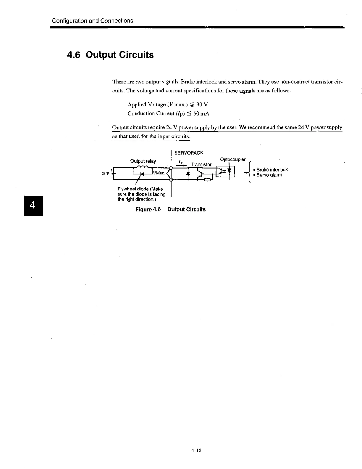
There are two output signals: Brake interlock and servo alarm. They use non-contract transistor cir-
cuits. The voltage and current specifications for these signals are as follows:
Applied Voltage (V max.) 30 V
Conduction Current (/p) 50 mA
Output circuits require 24 V power supply by the user. We recommend the same 24 V power supply
as that used for the input circuits.
24 V
Output relay
Flywheel diode (Make
sure the diode is facing
the right direction.)
SERVOPACK
I,
Transistor
Figure 4.6 Output Circuits
Optocoupler
.....1 • Brake interlock
• Servo alarm
4 -18

 Loading...


