6.2 I/O Signal Allocations
6.2.1 Input Signal Allocations
6-4
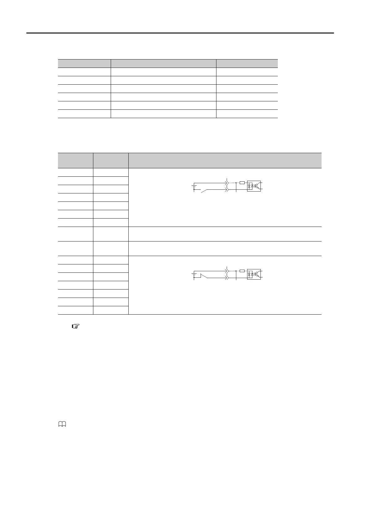
Relationship between Parameter Settings, Allocated Pins, and Polarities
The following table shows the relationship between the input signal parameter settings, the
pins on the I/O signal connector (CN1), and polarities.
Note: Refer to the following section for details on input signal parameter settings.
9.2.2 List of Parameters on page 9-4
Example of Changing Input Signal Allocations
The following example shows reversing the P-OT (Forward Drive Prohibit) signal allocated to
CN1-42 and the /P-CL (External Torque Limit) signal allocated to CN1-45.
Refer to the following manual for the parameter setting procedure.
Σ-7-Series Σ-7S SERVOPACK with Analog Voltage/Pulse Train References Product Manual (Manual No.: SIEP
S800001 26)
/SEL4
Program Step Selection Input 4
Pn632 = n.
X
/JOGP
Forward Jog Input
Pn632 = n.
X
/JOGN
Reverse Jog Input
Pn632 = n.
X
/JOG0
Jog Speed Table Selection Input 0
Pn632 = n.X
/JOG1
Jog Speed Table Selection Input 1
Pn633 = n.
X
/JOG2
Jog Speed Table Selection Input 2
Pn633 = n.
X
Parameter
Setting
Pin No. Description
040
A reverse signal (a signal with “/” before the signal abbreviation, such as the /
S-ON signal) is active when the contacts are ON (closed).
A signal that does not have “/” before the signal abbreviation (such as the P-
OT signal) is active when the contacts are OFF (open).
141
242
343
444
545
646
7–
The input signal is not allocated to a connector pin and it is always active.
If the signal is processed on a signal edge, then it is always inactive.
8–
The input signal is not allocated to a connector pin and it is always inactive.
Set the parameter to 8 if the signal is not used.
940
A reverse signal (a signal with “/” before the signal abbreviation, such as the /
S-ON signal) is active when the contacts are OFF (open).
A signal that does not have “/” before the signal abbreviation (such as the P-
OT signal) is active when the contacts are ON (closed).
A41
B42
C43
D44
E45
F46
Pn50A = n.2
0 Pn50B = n.
5
Before change
↓↓
Pn50A = n.5
1 Pn50B = n.
2
After change
Continued from previous page.
Input Signal Input Signal Name Parameter
 Loading...


