5 Installation Procedure
YASKAWA ELECTRIC TOBP C730600 24D 1000-Series Option SI-S3/V, SI-S3/T Installation Manual 19
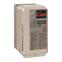
◆ Wiring the CANopen Option
The CANopen option must be connected to the network using a 9 pin D-sub connector like
shown in Figure 6.
Figure 6
Figure 6 Wiring Diagram
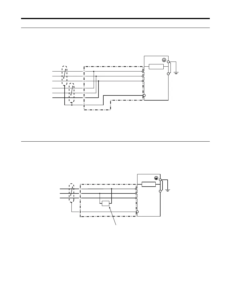
◆ Termination
Both ends of a CANopen bus system have to be terminated with a 120 Ω resistor. As the
CANopen Option has no build in terminating resistor, make sure to apply a terminating
resistor as shown in Figure 7 if the CANopen Option is the last node in the network.
Figure 7
Figure 7 Terminating Diagram
<1> The FE terminal on the CANopen Option must be connected to the drive ground terminal using one of the 4
delivered ground wires.
<1> The FE terminal on the CANopen Option must be connected to the drive ground terminal using one of the 4
delivered ground wires.
D-sub Connector
CAN
_
SHLD
CAN
_
L
CAN
_
GND
CAN
_
H
CANopen Cable Connector
(Shell)
CANopen Cable
Drive
CANopen
Option
7
2
3
CN5
FE
<1>
Drive
D-sub Connector
CANopen
Option
CAN
_
SHLD
CAN
_
L
CAN
_
GND
CAN
_
H
7
2
3
CANopen Cable Connector
CN5
FE
(Shell)
<1>
CANopen Cable
120
Ω
For the last node on the network,
apply a terminating resister.

 Loading...