4 Inputs and Outputs
4.4.2 Using a Linear Servo Motor
19
4.4.2 Using a Linear Servo Motor
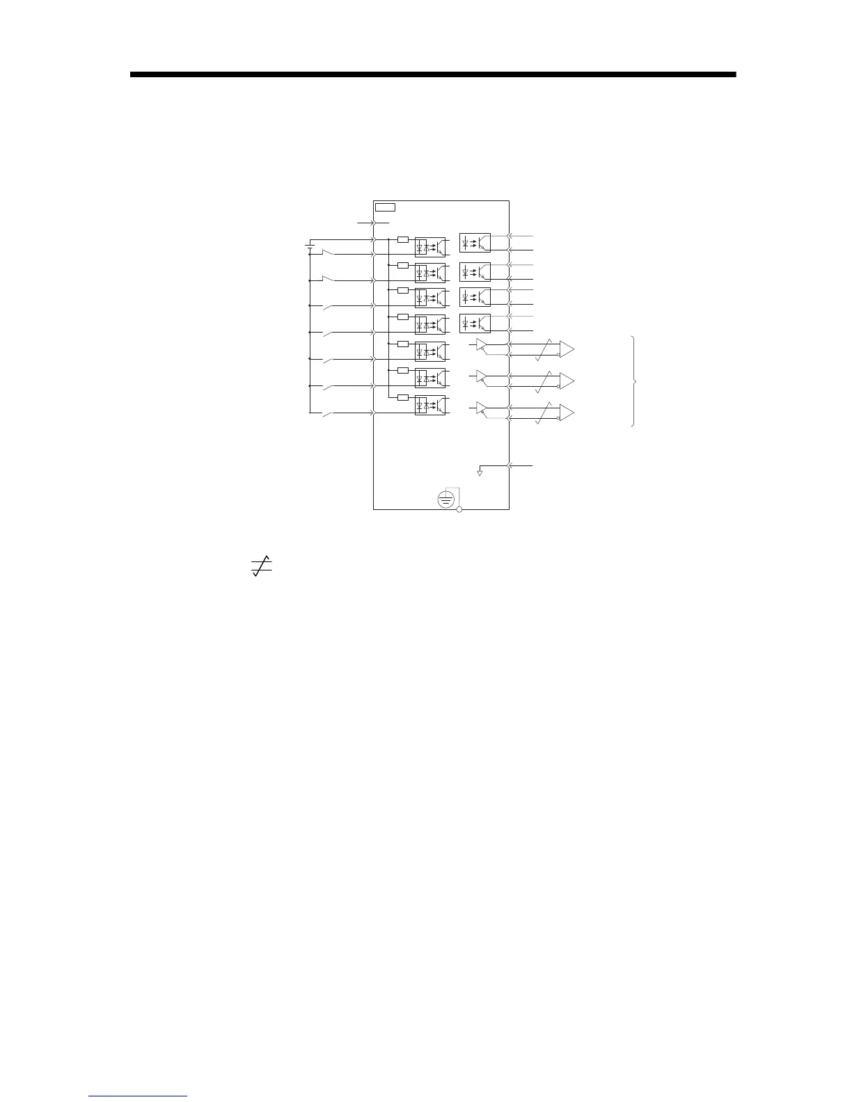
* 1. represents twisted-pair wires.
* 2. The 24-VDC power supply is not provided by Yaskawa. Use a 24-VDC power supply with
double insulation or reinforced insulation.
* 3. Always use line receivers to receive the output signals.
Note: 1. You can use parameters to change the functions allocated to the /SI0, /SI3,
P-OT, N-OT, /EXT1, /EXT2, and /EXT3 input signals and the /SO1, /SO2,
and /SO3 output signals.
2. If you use a 24-V brake, install a separate power supply for the 24-VDC
power supply from other power supplies, such as the one for the I/O signals
of the CN1 connector.
If the power supply is shared, the I/O signals may malfunction.
/BK+
/BK-
/SO2+
/SO2-
/SO3+
ALM+
ALM-
1
2
23
24
3
4
+24VIN
+24 V *2
6
8
10
9
11
12
/SI0
P-OT
N-OT
13
7
/SO3-
25
26
16
SG
*1
PBO
PCO
/PBO
PAO
/PAO
/PCO
21
17
18
19
20
22
FG
CN1
*3
*3
*3
4.7 k
Ω
TH
5
General-purpose
sequence input 0
Forward Drive Prohibit input
(prohibited when OFF)
Linear Servomotor overheat
protection input
Reverse Drive Prohibit input
(prohibited when OFF)
Brake output
(released when ON)
Servo Alarm Output
(OFF for alarm)
Photocoupler outputs
Max. allowable voltage: 30 VDC
Max. allowable current: 50 mA DC
Encoder Divided
Pulse Output,
Phase A
Encoder Divided
Pulse Output,
Phase B
Encoder Divided
Pulse Output,
Phase C
Applicable Line Receiver:
SN75ALS175 or MC3486
manufactured by Texas
Instruments or the equivalent
Connect shield to connector shell.
Connector
shell
SERVOPACK
Frame ground
Sequence input signal
power supply input
/SI3
/EXT1
/EXT2
/EXT3
General-purpose
sequence input 3
External latch signal 1 input
(General purpose input 4)
External latch signal 2 input
(General purpose input 5)
External latch signal 3 input
(General purpose input 6)