4 Inputs and Outputs
4.5.2 Sequence Output Circuits
21
4.5.2 Sequence Output Circuits
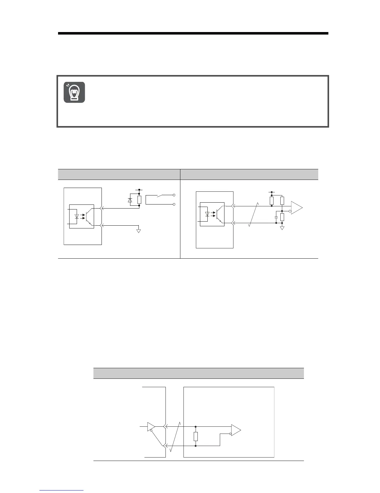
Photocoupler Output Circuits
Photocoupler output circuits are used for the ALM (Servo Alarm), /S-RDY (Servo
Ready), and other sequence output signals. Connect a photocoupler output circuit
to a relay or line-receiver circuit.
Note: The maximum allowable voltage and current range for photocoupler output circuits are
as follows:
• Maximum allowable voltage: 30 VDC
• Current range: 5 mA to 50 mA DC
Line-Driver Output Circuits
This section describes CN1 connector terminals 17-18 (Phase-A Signal), 19-20
(Phase-B Signal), and 21-22 (Phase-C Signal).
The serial data from the encoder is converted to two-phase (phases A and B)
pulses. The resulting output signals (PAO, /PAO and PBO, /PBO) and origin pulse
signal (PCO and /PCO) are output with line-driver output circuits. Connect the line-
driver output circuits to line-receiver circuits at the host controller.
Incorrect wiring or incorrect voltage application to the output circuits
may cause short-circuit failures.
If a short-circuit failure occurs as a result of any of these causes, the
holding brake will not work. This could damage the machine or cause
an accident that may result in death or injury.
Example for Relay Circuit Example for Line-Receiver Circuit