6-20
The following only applies to Inverters with SPEC: E or later.
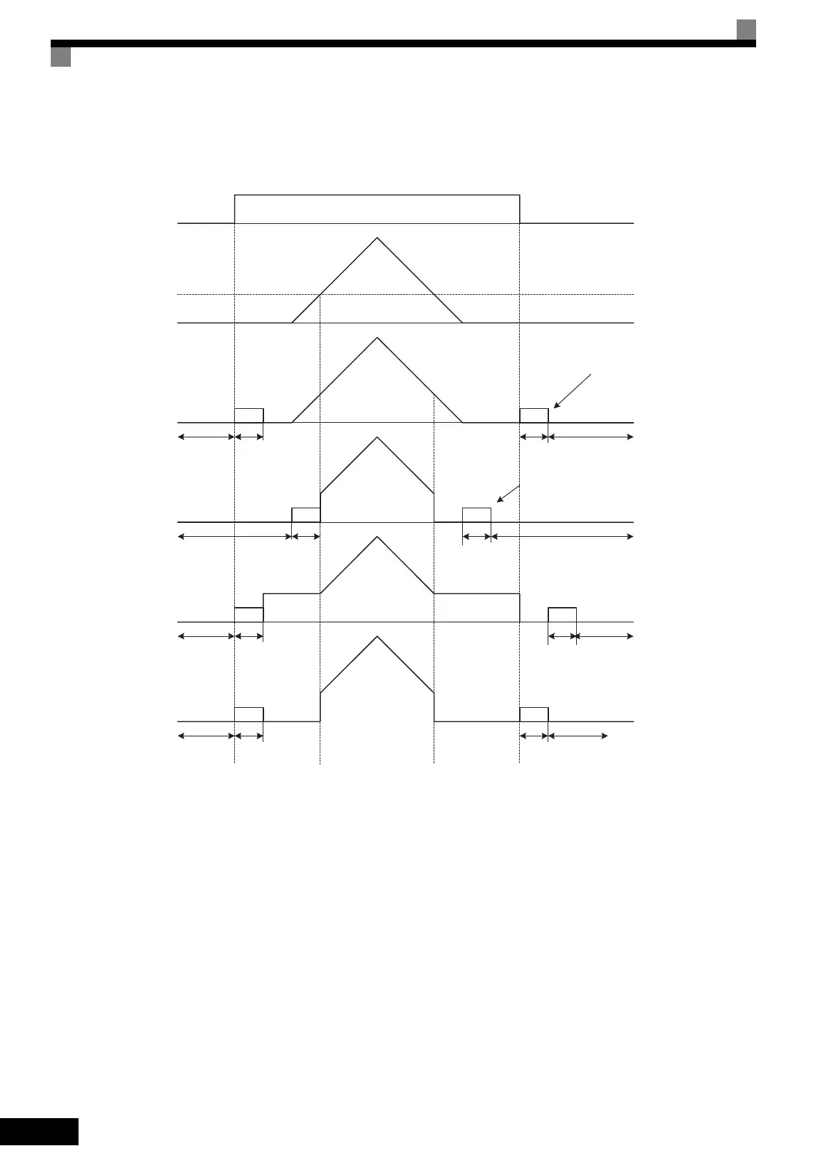
The operation after starting or stopping depends on the setting of b1-05 when flux vector control is selected
(A1-02 = 3).
Fig 6.16 Deceleration to Stop (for Flux Vector Control)
Setting Precautions
• When using flux vector control, the zero-speed control starts when motor speed drops to b2-01 during
deceleration. Also, the setting b2-01 < E1-09 is possible.
• The current level during injection brake time at start is the value of E2-03 (motor no-load current). Accord-
ingly, b2-02 is invalid in flux vector control.
Injection brake
time at start
b2-03
Zero-speed
control
b2-04
Baseblock
b2-03
b2-04
b2-03
b2-04
b2-03 b2-04
Run Command
OFF ON OFF
Frequency reference
via analog input
0
E1-09
b1-05=0
(frequency reference)
Run Command turns OFF
and zero-speed control starts
when motor speed drops to b2-01.
b1-05=1
(Coast)
b1-05=2
(Run on E1-09)
b1-05=3
(Zero-speed)
Injection brake
time at start
Injection brake
time at start
Injection brake
time at start
Baseblock
Baseblock
Baseblock
Baseblock
Baseblock
Baseblock
Baseblock
Zero-speed
control
Zero speed control
Zero-speed control
Frequency reference drops to less
than E1-09 and zero-speed control
starts when motor speed drops to
b2-01.
Run Command turns OFF
and zero-speed control starts
when motor speed drops to b2-01.
Run Command turns OFF
and zero-speed control starts
when motor speed drops to b2-01.

 Loading...


