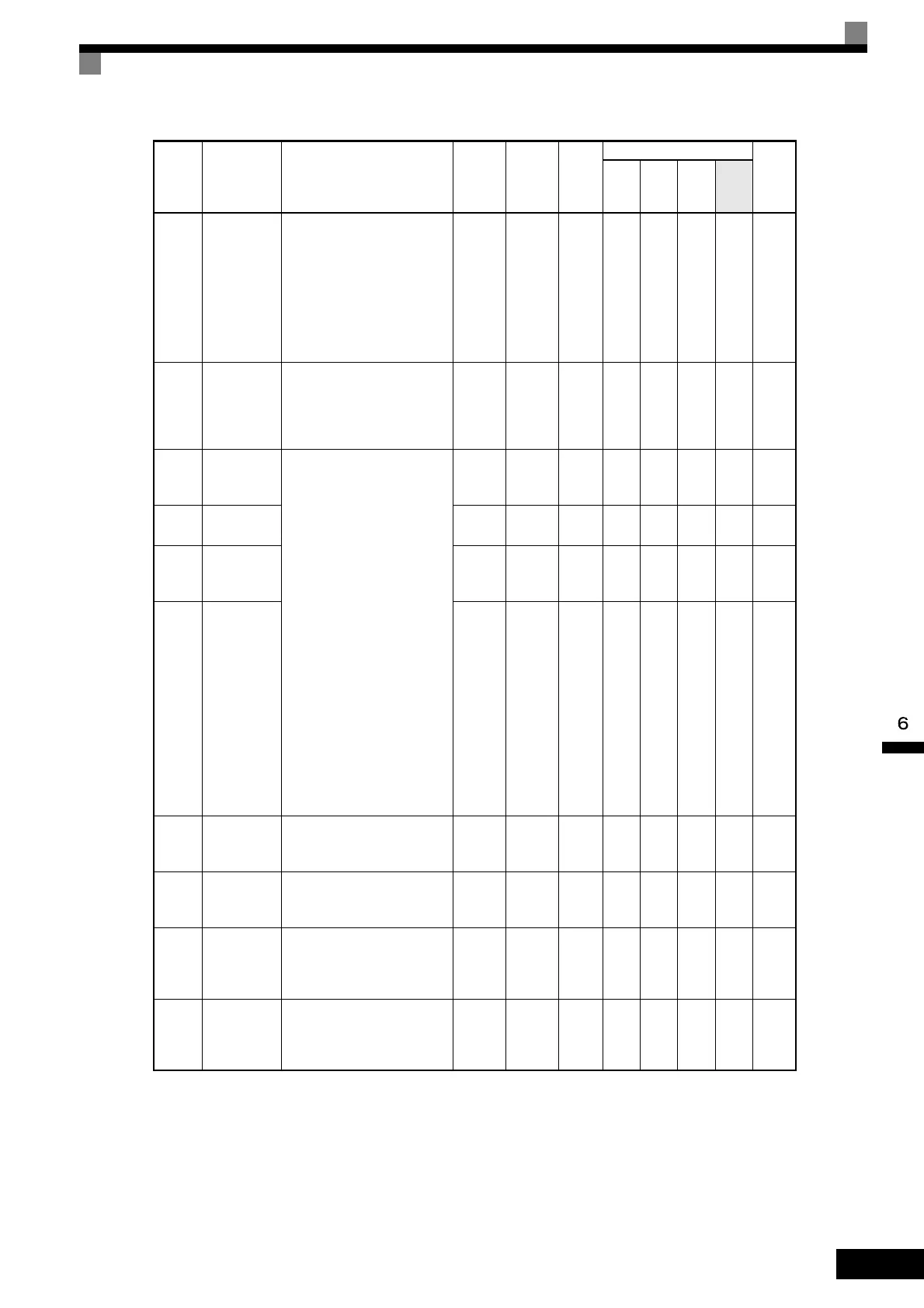
Monitor Constants
6-91
H4-06
Bias (termi-
nal AM)
Sets the multi-function analog
output 2 voltage level bias.
Sets output characteristic up/
down parallel movement as a
percentage of 10 V.
The maximum output from the
terminal is 10 V.
A meter calibration function is
available.
-10.0 to
+10.0
0.0% Yes A A A A 422H
H4-07
Analog out-
put 1 signal
level selec-
tion
Sets the signal output level for
multi-function output 1 (termi-
nal FM)
0: 0 to +10 V output
1: 0 to ±10 V output
0 or 1 0 No A A A A 423H
F4-01
Channel 1
monitor
selection
Effective when the Analog
Monitor Board is used.
Monitor selection:
Set the number of the monitor
item to be output. (U1-)
The monitor items that can be
set depends on the control
method.
Gain:
Set the multiple of 10 V for out-
putting monitor items.
4, 10 to 14, 25, 28, 31, 34, 35,
39, 40, 42 cannot be set. 29 to 31
are not used. When the AO-12
Analog Monitor Board is used,
outputs of ± 10 V are possible.
To output ± 10 V, set F4-07 or
F4-08 to 1. When the AO-08
Analog Monitor Board is used,
only outputs of 0 to +10 V are
possible.
A meter calibration function is
available.
1 to 99 2 No A A A A 391H
F4-02
Channel 1
gain
0.00 to
2.50
1.00 Yes A A A A 392H
F4-03
Channel 2
monitor
selection
1 to 99 3 No A A A A 393H
F4-04
Channel 2
gain
0.00 to
2.50
0.50 Yes A A A A 394H
F4-05
Channel 1
output moni-
tor bias
Sets the channel 1 item bias to
100%/10 V when the Analog
Monitor Board is used.
-10.0 to
10.0
0.0% Yes A A A A 395H
F4-06
Channel 2
output moni-
tor bias
Sets the channel 2 item bias to
100%/10 V when the Analog
Monitor Board is used.
-10.0 to
10.0
0.0% Yes A A A A 396H
F4-07
Analog out-
put signal
level for
channel 1
0: 0 to 10 V
1: -10 to +10 V
0 or 1 0 No A A A A 397H
F4-08
Analog out-
put signal
level for
channel 2
0: 0 to 10 V
1: -10 to +10 V
0 or 1 0 No A A A A 398H
Con-
stant
Number
Name Description
Setting
Range
Factory
Setting
Change
during
Opera-
tion
Control Methods
MEMO
BUS
Regis-
ter
V/f
V/f
with
PG
Open
Loop
Vec-
tor
Flux
Vec-
tor

 Loading...


