6-92
Selecting Analog Monitor Items
The digital operator monitor items (U1- [status monitor]) are output from multi-function analog output
terminals FM-AC and AM-AC. Refer to Chapter 5 User Constants, and set the values for the part of U1-
(status monitor).
Alternatively, you can output monitor items (U1- [status monitor]) from analog output option terminal
channels 1 and 2 on analog monitor boards AO-08 and AO-12. Refer to the table of constants, and set the val-
ues.
Adjusting the Analog Monitor Items
Adjust the output voltage for multi-function analog output terminals FM-AC and AM-AC using the gain and
bias in H4-02, H4-03, H4-05, and H4-06. Also, adjust the output voltage for output channels 1 and 2 of Ana-
log Output option boards AO-08 and AO-12 using the gain and bias in F4-02, F4-04, F4-05, and F4-06.
Adjusting the Meter
The output voltage for terminals FM-AC and AM-AC and output channels 1 and 2 of the AO option board can
be adjusted while the Inverter is stopped. For example, just pressing the Enter Key and displaying the data set-
ting display for H4-02 or H4-03 will cause the following voltage to be output by the FM-AC terminals.
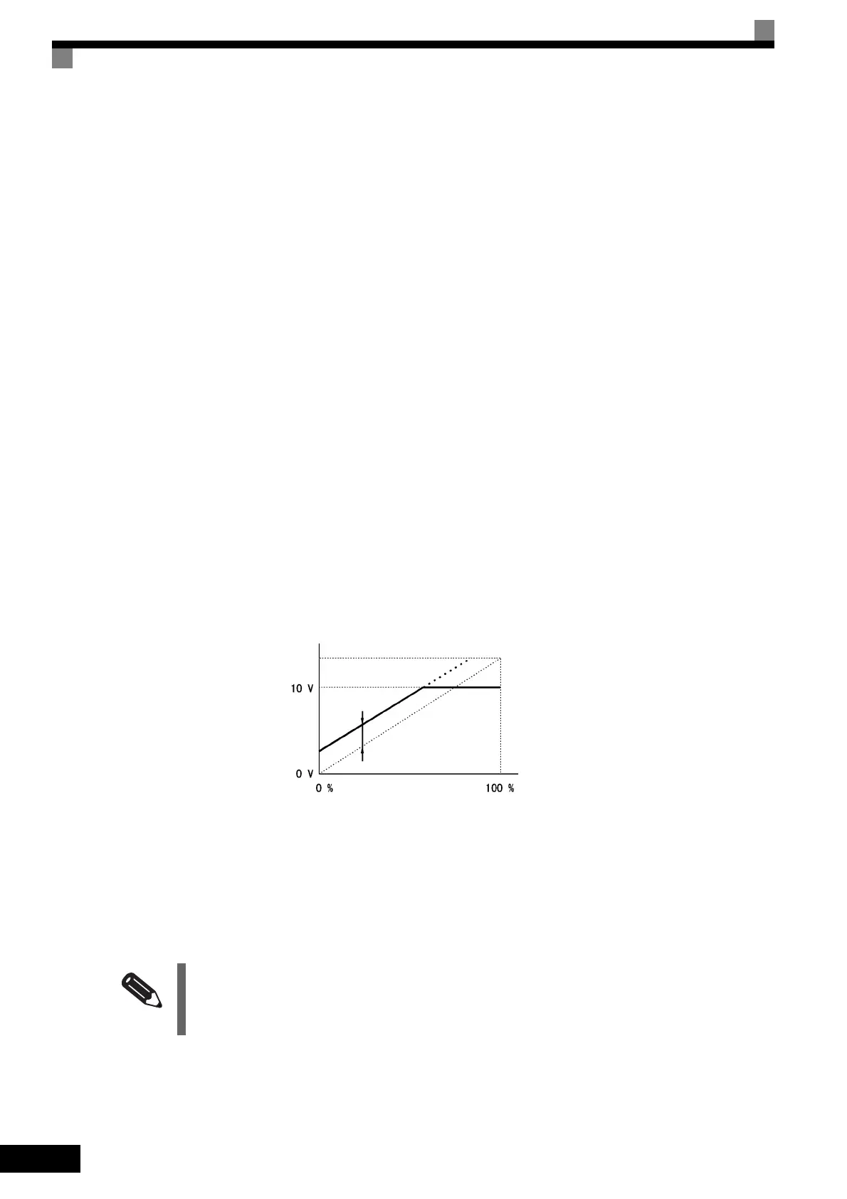
10 V/100% monitor output × output gain (H4-02) + output bias (H4-03)
Just pressing the Enter Key and displaying the data setting display for F4-02 or F4-05 will cause the following
voltage to be output to channel 1 of the AO option board.
10 V/100% monitor output × output gain (F4-02) + output bias (F4-05)
Fig 6.56 Monitor Output Adjustment
Switching Analog Monitor Signal Levels
Monitor items corresponding to 0 to ±10 V output 0 to 10 V signals when the monitor value is positive (+),
and 0 to -10 V signals when the monitor value is negative (-). For monitor items corresponding to 0 to ±10 V,
refer to Chapter 5 User Constants.
INFO
You can select the signal levels separately for multi-function analog output terminals and analog output option
terminals.
Output voltage
Gain x 10 V
Bias x 10/100 V
Monitor item

 Loading...


