6-130
Multi-function Contact Input Functions (H1-01 to H1-06)
Multi-function Contact Output Functions (H2-01 to H2-03)
Multi-function Analog Inputs (H3-05, H3-09)
Monitor Function
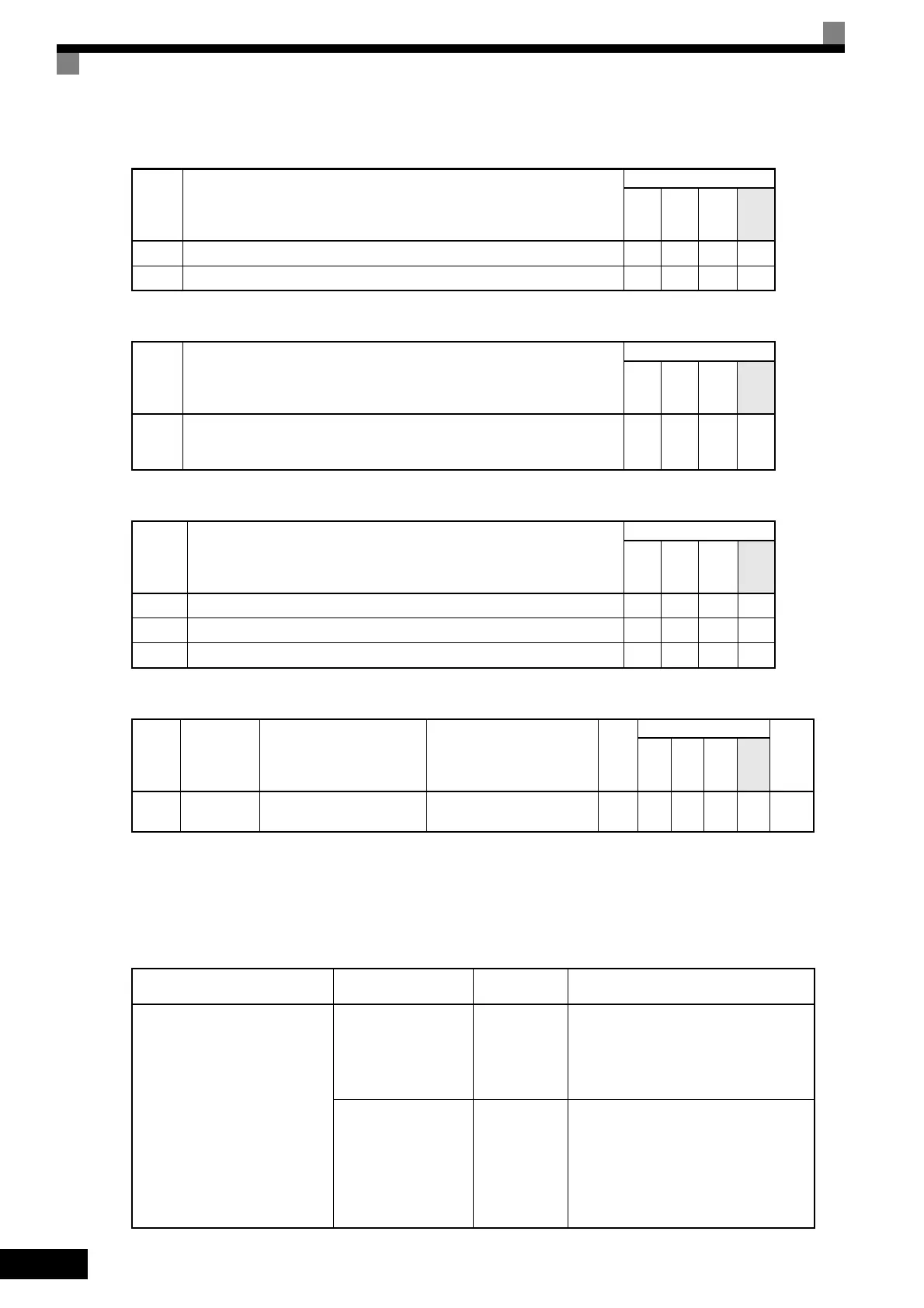
Inputting Torque References and Torque Reference Directions
The torque reference can be changed according to an analog input by setting H3-09 (Multi-function analog
input terminal A2 selection) or H3-05 (Multi-function analog input terminal A3 selection) to 13 (torque refer-
ence) or 14 (torque compensation). The torque reference input methods are listed in the following table.
Set-
ting
Value
Function
Control Methods
V/f
V/f
with
PG
Open
Loop
Vec-
tor
Flux
Vec-
tor
71 Speed/torque control change (ON: Torque control) No No No Yes
78 Polarity Reverse Command for external torque reference No No No Yes
Set-
ting
Value
Function
Control Methods
V/f
V/f
with
PG
Open
Loop
Vec-
tor
Flux
Vec-
tor
32
Speed control circuit operating for torque control (except when stopped).
The external torque reference will be limited if torque control is selected.
Output when the motor is rotating at the speed limit.
No No No Yes
Set-
ting
Value
Function
Control Methods
V/f
V/f
with
PG
Open
Loop
Vec-
tor
Flux
Vec-
tor
0 Add to terminal A1 Yes Yes Yes Yes
13 Torque reference/torque limit at speed control No No No Yes
14 Torque compensation No No No Yes
Con-
stant
Number
Name Description
Output Signal Level Dur-
ing Multi-Function Analog
Output
Min.
Unit
Control Methods
MEMO
BUS
Regis-
ter
V/f
V/f
with
PG
Open
Loop
Vec-
tor
Flux
Vec-
tor
U1-09
Torque refer-
ence
Monitor in internal torque ref-
erence value for vector control.
10 V: Motor rated torque
(0 to ± 10 V possible)
0.1% No No A A 48H
Torque Reference Input
Method
Reference Location
Selection
Method
Remarks
Voltage input (0 to
±10 V)
Between A3 and AC
H3-04 = 1
H3-05 = 13
Set H3-04 to 0 for a 0 to 10-V torque ref-
erence.
To switch the torque reference between
positive and negative torque, set a multi-
function analog input to 78.
Between A2 and AC
(Turn OFF pin 2 of
SW1.)
H3-08 = 1
H3-09 = 13
Set H3-08 to 0 for a 0 to 10-V torque ref-
erence.
To switch the torque reference between
positive and negative torque, set a multi-
function analog input to 78.
The input can be used for torque compen-
sation by setting H3-09 to 14.

 Loading...


