Wiring Main Circuit Terminals
2-11
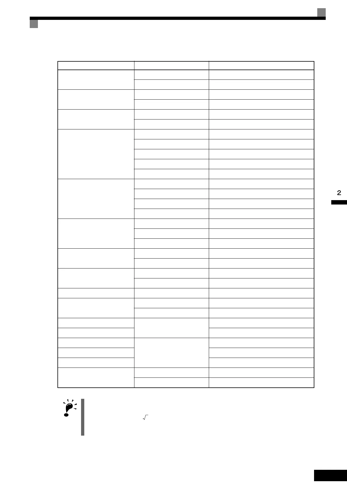
Table 2.3 Closed-loop Connector Sizes (JIS C2805) (200 V Class and 400 V Class)
Wire Thickness (mm
2
)
Terminal Screws Size
0.5
M3.5 1.25 to 3.5
M4 1.25 to 4
0.75
M3.5 1.25 to 3.5
M4 1.25 to 4
1.25
M3.5 1.25 to 3.5
M4 1.25 to 4
2
M3.5 2 to 3.5
M4 2 to 4
M5 2 to 5
M6 2 to 6
M8 2 to 8
3.5/5.5
M4 5.5 to 4
M5 5.5 to 5
M6 5.5 to 6
M8 5.5 to 8
8
M5 8 to 5
M6 8 to 6
M8 8 to 8
14
M6 14 to 6
M8 14 to 8
22
M6 22 to 6
M8 22 to 8
30/38 M8 38 to 8
50/60
M8 60 to 8
M10 60 to 10
80
M10
80 to 10
100 100 to 10
100
M12
100 to 12
150 150 to 12
200 200 to 12
325
M12 x 2 325 to 12
M16 325 to 16
IMPORTANT
1. Determine the wire size for the main circuit so that line voltage drop is within 2% of the rated voltage. Line
voltage drop is calculated as follows:
Line voltage drop (V) =
x wire resistance (W/km) x wire length (m) x current (A) x 10
-3
2. Use a closed-loop connector (made by J.S.T. Mfg. Co., Ltd. or an equivalent) for the main circuit input and
output terminals of Inverters of 200V 11 kW or more and those of 400V 22 kW or more.
3

 Loading...


