15
VENTING
Venting the flue products safely is a key
concern when installing any gas-fired appliance,
including Yazaki chiller-heaters. Rules for the
proper venting of gas-fired appliances are
covered in the National Fuel Gas Code, NFPA
Section 54. Consult NFPA for full venting details.
For chimney design purposes, the exhaust
gas flow rate for the CH-K100 is 303 cfm (46.3
m³/hr). This reflects input fuel rate operating at
high fire with proper combustion air supply, with
CO at 8.5%, O
2
at 5.5%, and no more than 40%
excess air (32% is ideal). Venting gases will be
approximately 392°F (200°C) at a density of
0.011 lbs/ft³.
Exhaust Gas Volume – CFM
(m³/hr)
All CH-K series chiller-heaters are Category I
appliances. When choosing vent material size,
the chillers-heaters are classified as “fan” vent
type since the fan on the burner assists in moving
flue products through the unit. The fan does NOT
provide enough force to do more than push the
flue products a few feet down the vent, so it does
not have enough force to qualify as Category III,
side discharge venting. There are aftermarket
kits that can provide Category III capability for
Category I appliances should the need arise, but
Yazaki offers no kit for this. Warranty may be
void on the Yazaki chiller-heater if such a kit is
used, but not installed or applied correctly.
Carefully follow all instructions when applying
these kits and if necessary contact Yazaki Energy
Systems, Inc. for guidance on integration of the
kit to the unit control safeties.
A number of quick rules can be listed in
regard to venting:
1. Always use B-Type double wall vent material.
2. Vent should never run downhill.
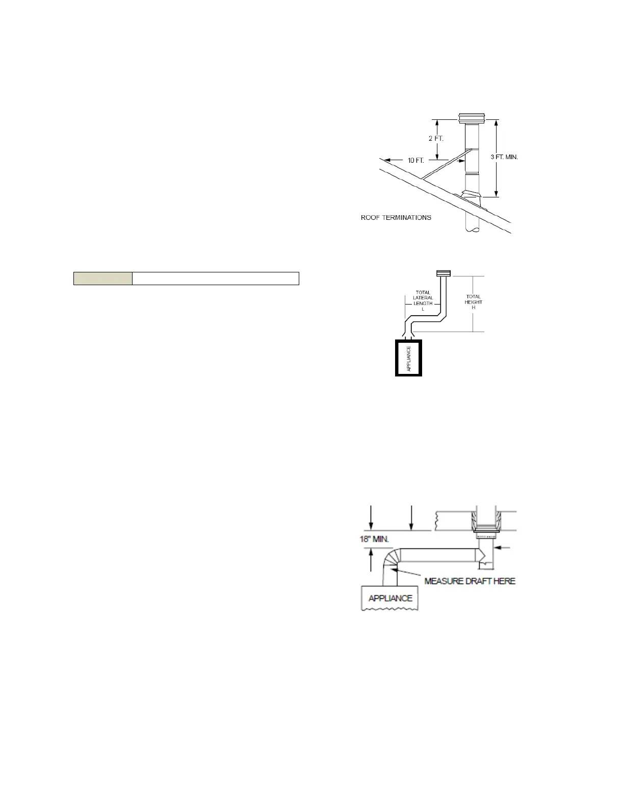
3. Vent must terminate at least 7’ above public
walkways.
4. Vent must terminate at least 4’ above
vertically or 10’ horizontally from openings
into living areas or air intakes.
5. Vent must terminate no closer than 10’ from
an inside corner unless it terminates 2’ above
said inside corner.
6. Vent should terminate at least 2’ above the
highest point within 10’.
7. Rise (Height) should be greater than the Run
(Lateral).
8. It is recommended that each unit be vented
separately if possible. The range of draft
pressure allowed at the vent connection
exiting the chiller-heater is 0.0” wc to -0.05”
wc. Regardless of installation indoor or
outdoor, if the draft pressure is outside of this
range, a barometric damper (aka: draft regulator)
must be used to correct this in order to
prevent sooting and possible damage to the
High Temperature Generator
(HGE).
In instances where multiple units are to be
vented, and individual venting is impractical or
undesirable, combined venting (Common
Venting) is permitted so long as it follows proper
venting rules. It should be noted that there will
be separate and special charts for sizing common
venting applications. Follow the rules given by
the vent material manufacturer.
CH-K100 360 (612)