20
ELECTRICAL
Electrical
Power Supply 208V or 230V / 60 Hz / 3-Phase
Consumption Watts 2500
Minimum Circuit Amps Amps 18.6
Maximum Over-Current
Protection
Amps 20
Power Consumption does not include external pumps or cooling tower fan motors.
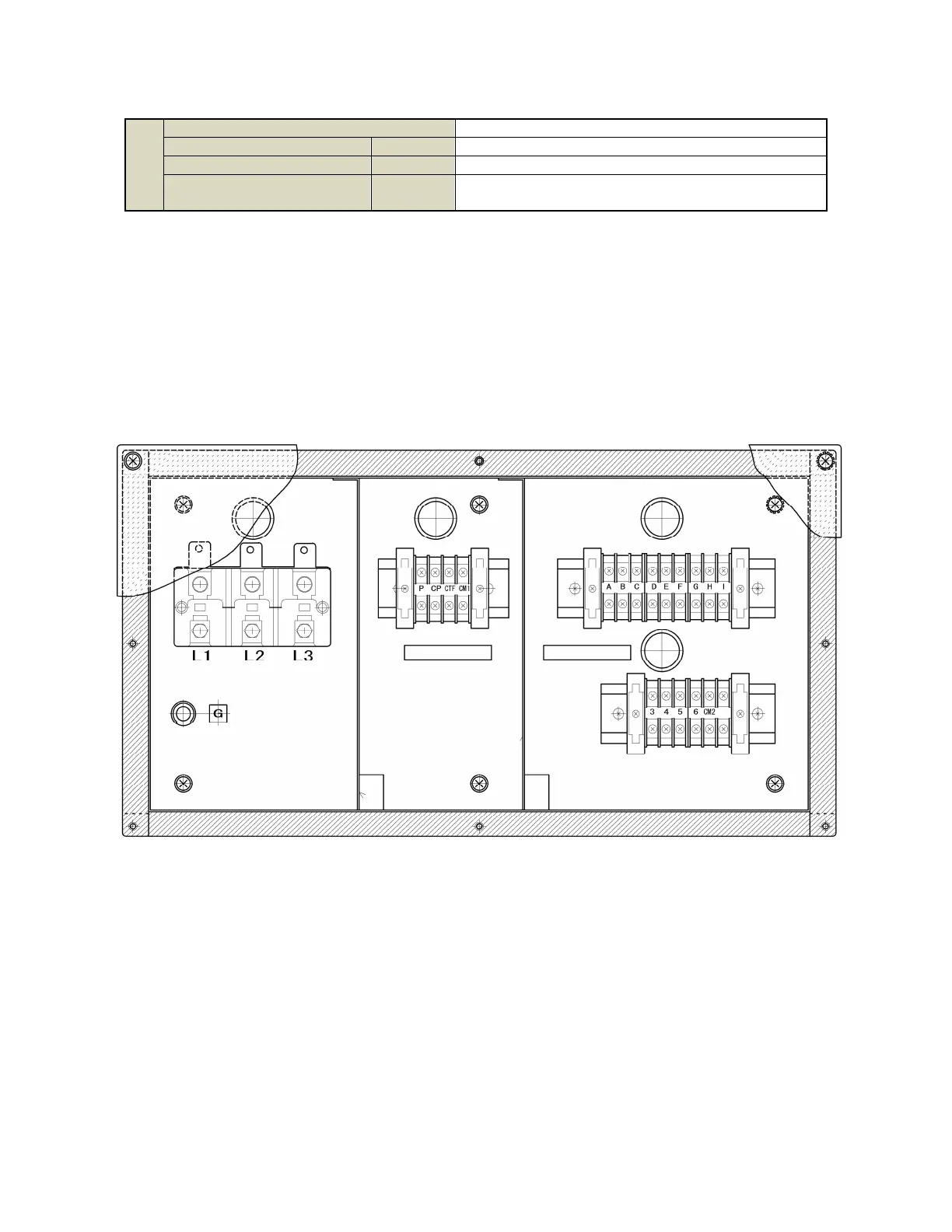
Each chiller-heater has a junction box located
at the rear of the unit. This junction box is a
single point where all external electrical
connections terminate.
High voltage connections should be made to
L1, L2, L3, and G. The power leg that has the
highest voltage reading to G should be
terminated on L2.
A rotation test must be performed as well.
Clockwise rotation lead end is desired. If
incorrect rotation is discovered, swap L1 and L3
wires to reverse the rotation. A rotation meter is
the simplest method to determine rotation.
The center section of the junction box
contains the pump controls. Supply voltage is
provided from a field-supplied 24V transformer to
terminal CM1. The unit will take that voltage and
route it to terminal P when there is a chilled/hot
water pump demand. It will take that same
voltage and route it to terminal CP when there is
a demand for the cooling water pump. It will use
that same voltage to cycle the cooling tower fan,
applying that voltage to CTF when the incoming
cooling water is at 84.2°F (29°C) or greater, and
taking it away when the incoming cooling water
drops to 80.5°F (27°C). This logic function of
cooling water temperature control is provided for
convenience, and is not intended to supersede
more sophisticated controls such as VFD fan
controls, etc.
Terminals A through I in the upper right
section of the junction box are intended for use
with the optional Yazaki Remote Control Panel.
However, these terminals can also be used to
interface with Building Management Systems.