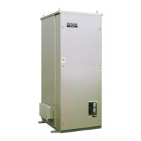
YAZAKI CH-K SERIES CHILLER-HEATER
INSTALLATION CHECK AND REQUEST FOR START-UP
Yazaki Service Provider:
Address:
Project Name:
Project Address:
A. CHILLER-HEATER
1. Unit placed on foundation □
2. Unit leveled properly □
3. Changeover Valve Actuator installed □
4. Service clearance provided on all
sides and top (40 in. front) □
5. Chiller-heater anchored by L-Anchor
plates to foundation (if required) □
B. WATER PIPING
1. Chilled/hot water piping installed
between chiller-heater, pumps and
air handling unit(s) □
2. Cooling water piping installed
between chiller-heater, pumps, and
cooling tower □
3. Flow switch piping attached □
4. Water piping leak tested and flushed □
5. System filled with water and glycol
(if required) and trapped air vented □
6. Flow setters installed in water piping □
7. Test plugs (Pete’s plugs) and/or
thermowells installed in the inlet and outlet
piping of each chiller-heater □
8. Valves installed at each chiller-heater
for flow balancing and isolation □
9. Air vent valves installed on piping □
10. Strainers present and clean □
11. Expansion tank (properly charged) and
water make-up piping installed to
chilled/hot water system □
12. Water make-up and fill lines installed
to the cooling tower □
13. Pressure relief valves, set at 150 psi
(max.) installed on piping adjacent to
each chiller-heater (if required) □
C. GAS PIPING
1. Natural Gas supply is available
between 7” wc and 10.5” wc
…
……...□
2. Gas piping installation completed □
3. Gas cock and sediment trap installed □
4. Gas meter and appliance regulator
installed at each chiller- heater □
5. Gas pipe leak tested and purged □
D. VENTING
1. Factory-provided vent cap installed
(outdoor installation) □
2. Barometric damper and Type-B vent
extension installed on each chiller-heater
outlet (indoor installation) □
E. POWER WIRING
1. Power supply, indicated on the UNIT
NAMEPLATE, is connected □
2. Wiring completed between the chiller-
heater, motor contactors and the
following motors: Chilled/hot water
pump, cooling water pump and
cooling tower fan □
3. Rotation of each motor checked □
4. Power supply wiring connected
between a fused disconnect and
each chiller-heater. (DO NOT operate
the chiller-heater) □
5. Power supply available near the
chiller-heater for a vacuum pump □
F. CONTROL WIRING
1. Motor contactors and manual controls
installed for all external motors □
2. Control wiring installed between
chiller-heater and pump/motor
contactors □
3. Interlock wiring installed between
chiller-heater and thermal overloads
on the following motors: Chilled/hot
water pump, cooling water pump and
cooling tower fan □
4. Wiring installed between chiller-heater
and auxiliary contact on the cooling
tower fan motor contactor □
G. CONDITIONS
1. Personnel available to assist with
start-up who are familiar with the
system □
2. Adequate vacuum pump available
□
Model No: Serial No:
Anticipated Startup Date: