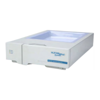
YL9120 UV/Vis Detector
Figure Contents
[Fig. 1] Pin configuration of each terminal............................................................................................... 5
[Fig. 2] Diagram of Remote and Marker input......................................................................................... 5
[Fig. 3] Diagram of Remote and Marker output....................................................................................... 6
[Fig. 4] Connection of communication cable ........................................................................................... 7
[Fig. 5] Front parts of YL9120 UV/Vis detector...................................................................................... 15
[Fig. 6] Tungsten lamp assembly........................................................................................................... 16
[Fig. 7] The diagram of Flow cell assembly........................................................................................... 17
L9120
ii

 Loading...