PERFORMANCE TEST
2 - 5
SM 700820-01E
2
Procedure
Output the signals at the following frequencies and output levels from the standard
signal generator and measure the output level with the power meter.
Output frequency Output level
0.1 MHz –20 dBm, 10 dBm
20.02 MHz –20 dBm, 10 dBm
150.02 MHz –20 dBm, 10 dBm
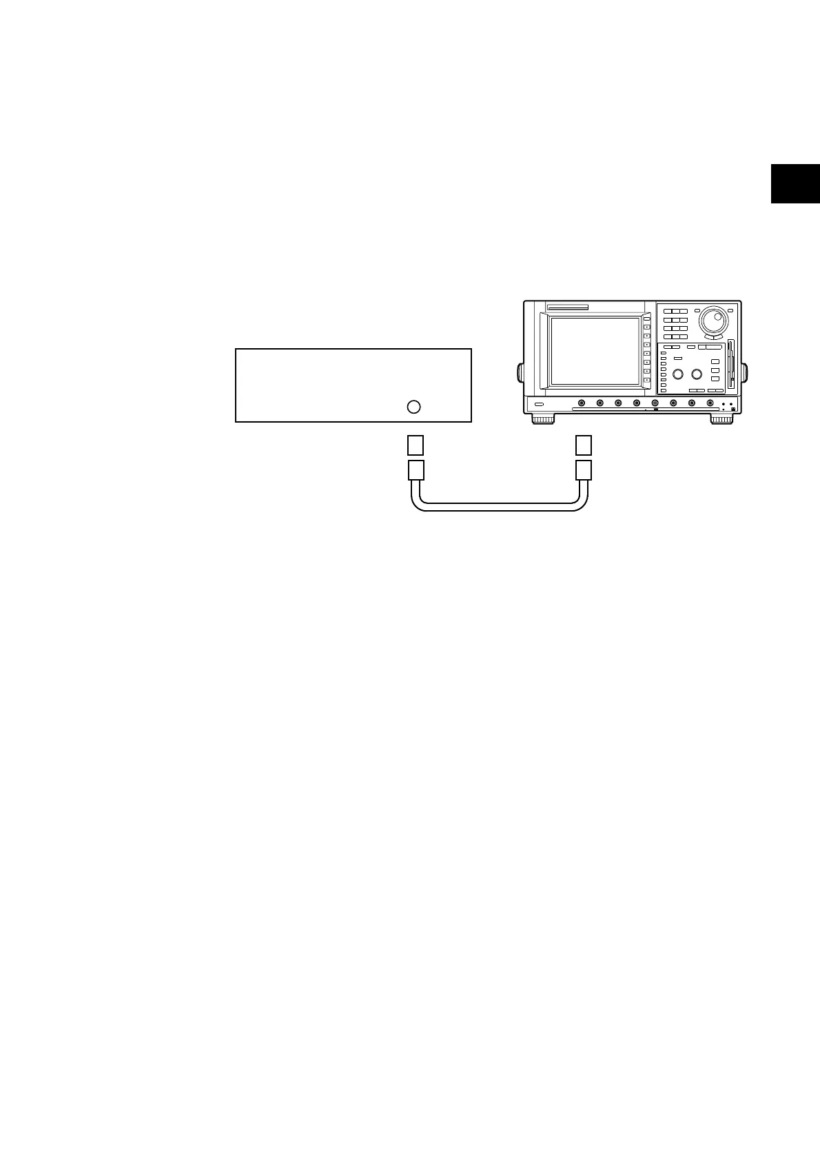
Connection
CH 1 to 8
50 ohm Termination
N-BNC
Conversion Adapter
Standard Signal Generator
Cable
DL2700
Procedure
1) Turn on the power source of the DL2700. After warm-up press the CAL key, then press
the “Calibration” soft key to calibrate the instrument.
Furthermore, press the INITIALIZE key, then press the “Initialize” soft key to initialize
the settings.
2) Set the DL2700 as shown below.
VERTICAL (for all channels)
V/DIV Set this according to the following measurement
conditions
PROBE 1:1
HORIZONTAL
TIME/DIV
0.1 MHz 5µs/div
20.02 MHz 20 ns/div
150.02 MHz 5 ns/div
TRIGGER SIMPLE
MODE NORMAL
SOURCE (Channel to be tested)
MEASURE
MODE ON
TRACE (Set to channel to be tested)
TIME RANGE Left –5 div
TIME RANGE Right +5 div
ITEM Select P-P
2.6 Frequency Response Test
 Loading...


