SM 700820-01E
2 - 6
3) Input the following voltages to the DL2700 oscilloscope, read the indications on the
DL2700 (Avg values), and compare the difference between these and the values mea-
sured by the power meter to the specified tolerances.
(i) Input sensitivity setting 20 mV/div Input level –20 dBm
(ii) Input sensitivity setting 500 mV/div Input level 10 dBm
Input frequency Permissible range
0.1 MHz ±1 dB
20.2 MHz ±1 dB
150.02 MHz +1, –3 dB
4) Test all channels in the same manner.
2.7 Time -base Accuracy Test
Specifications
±(0.01% + 500 ps)
Permissible range
50 kHz ± 10 kHz
Equipment required
Equipment Qty Mandatory specifications Recommended
Standard signal generator 1 Output frequency range HP 8657A
0.1 MHz to 150 MHz
50Ω terminator 1 HP 1251-2277
N-BNC conversion adaptor 1 N plug to BNC jack HP 1250-0780
Cable 1 BNC to BNC Yokogawa 3669 24
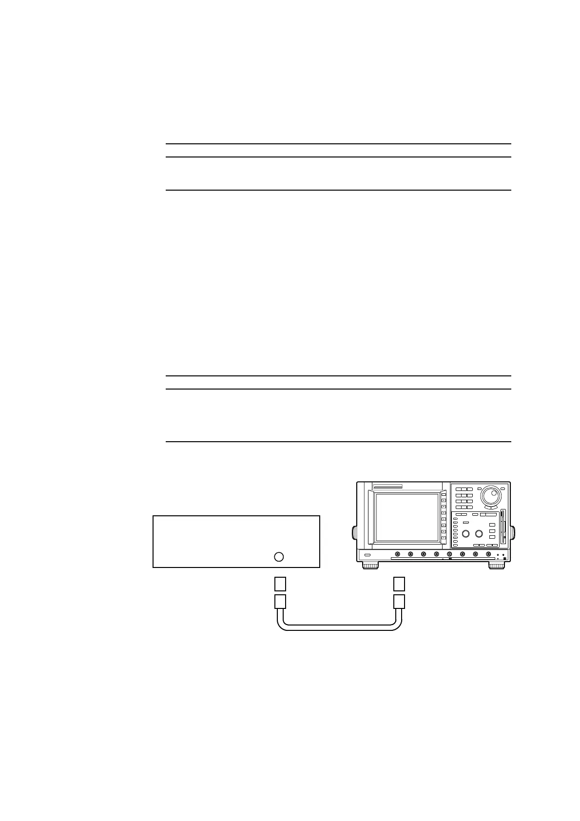
Connection
CH 1 to 8
50 ohm Termination
N-BNC
Conversion Adapter
Standard Signal Generator
Cable
DL2700
Procedure
1) Turn on the power source of the DL2700. After warm-up press the CAL key, then press
the “Calibration” soft key to calibrate the instrument.
Furthermore, press the INITIALIZE key, then press the “Initialize” soft key to initialize
the settings.
 Loading...


