SM 700820-01E
2 - 8
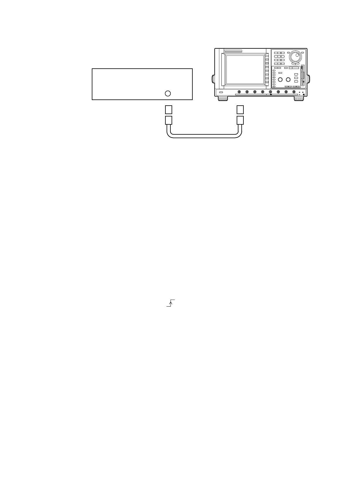
Connection
CH 1 to 8
50 ohm Termination
N-BNC
Conversion Adapter
Standard Signal Generator
Cable
DL2700
Procedure
1) Turn on the power source of the DL2700. After warm-up press the CAL key, then press
the “Calibration” soft key to calibrate the instrument.
Furthermore, press the INITIALIZE key, then press the “Initialize” soft key to initialize
the settings.
2) Set the DL2700 as shown below.
VERTICAL CH1
V/DIV 50 mV/div
COUPLING DC
PROBE 1:1
HORIZONTAL
TIME/DIV 10 ns
TRIGGER
MODE NORMAL
SOURCE CH1
COUPLING DC
SLOPE
DISPLAY
MAINFORMAT SINGLE
3) Input a 150 MHz signal with voltage amounting to 1 divp-p on the screen, and confirm
that the waveform stabilizes.
NOTE If the trigger is not actuated, vary the trigger level in the range of ± 40 mV and check
that the trigger is actuated.
4) Test all channels in the same manner.
2.9 Trigger Accuracy Test
Specifications
2 mV/div: ± (2 div. + 10% of the trigger level)
Other ranges: ± (1 div. + 10% of the trigger level)
 Loading...


