Specifications
Item Specifications
Output level CMOS level (0 to 5 V)
Output formats
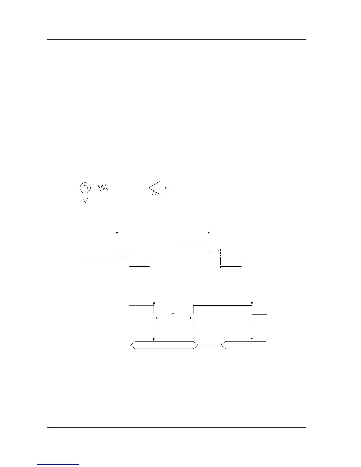
• Normal Logic Low when a trigger occurs and high after acquisition is completed
Output delay Within 1 μs + 1 sample period
Output hold
time
1 μs or more
• Pulse Logic Transmits a pulse when a trigger occurs
Output delay Within 1 μs + 1 sample period
Pulse width 1 ms, 50 ms, 100 ms, 500 ms
• Sample pulse Logic Transmits pulses at a given frequency during waveform acquisition
Pulse rate 5 Hz to 200 kHz (1-2-5 steps)
However, the interval must be longer than the instrument’s sampling
interval. The interval can be set to 1 over the integer multiple of the
instrument’s sampling interval.
• Start/Stop Logic High level output during waveform acquisition
Low level output while waveform acquisition is stopped
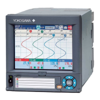
Circuit Diagram and Timing Chart for Trigger Out
Trigger Trigger
Connecting a Wire to the Terminal
For instruction on how to connect a wire to the terminal, see page 4-2.
4.2 Trigger Output (TRGO)
 Loading...