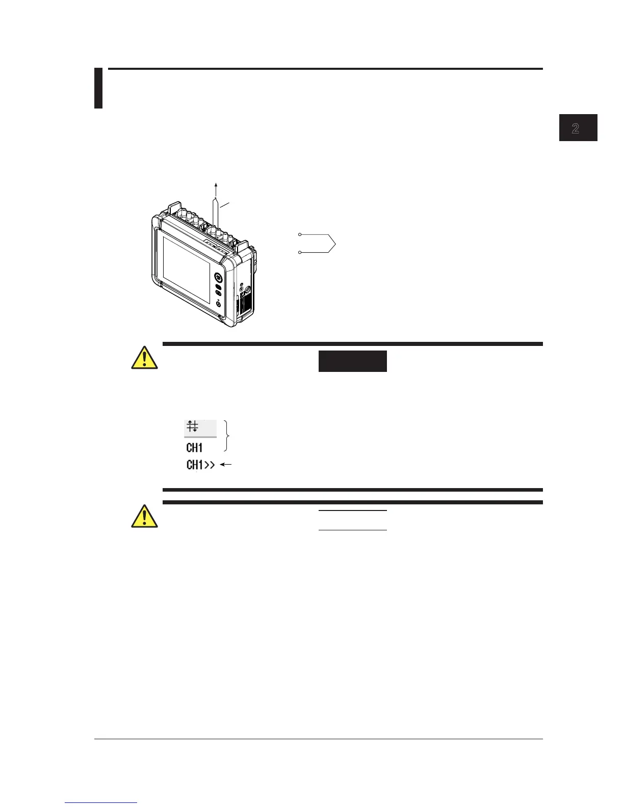
2.13 Connecting Thermocouples
Connecting Thermocouples
If you are connecting the compensation lead of the thermocouple to the input terminal (binding post
terminal) of the 701261 (UNIVERSAL), 701262 (UNIVERSAL (AAF)), 701265 (TEMP/HPV), or 720266
(TEMP/HPV), loosen the terminal knob, pass the lead through the terminal, and tighten the knob.
L
H
Positive lead
Negative lead
To the thermocouple
WARNING
If over-range is indicated, the instrument may be receiving a voltage higher than the observed
waveform or measured waveform values. To prevent electric shock, check the input voltage
level.
Over-range indication
Indicates the number of the channel that over-range is occurring on
Channel indication when over-range is occurring on multiple channels
Indicates the smallest number among the channels that over-range is occurring on
CAUTION
• 701261 (UNIVERSAL), 701262 (UNIVERSAL (AAF)), 701265 (TEMP/HPV), or 720266
(TEMP/HPV) is isolated from the instrument. However, applying a voltage exceeding the
value below may damage the input section. If the frequency is above 1 kHz, damage may
occur even when the voltage is below this value.
Maximum input voltage (across the input terminals, H and L, at a frequency of 1 kHz or
less)
42 V (DC + ACpeak)
Maximum rated voltage to ground (across the input terminal L and earth at a frequency of 1
kHz or less)
42 V (DC + ACpeak) (CAT II, 30 Vrms)
• Correct measurements cannot be obtained when the positive and negative thermocouple
leads are connected in reverse.
• Immediately after connecting the thermocouple, the heat balance may be disturbed at
the input terminal section and may cause measurement errors. Therefore, wait about 10
minutes before making a measurement.
 Loading...