2.11 Correcting the Probe Phase
For the following modules, always correct the probe phase before you use a probe for measurement.
• High-Speed 100 MS/s, 12-Bit Isolation Module: 720211 (HS100M12)
• High-Speed 10 MS/s, 12-Bit Isolation Module: 720250 (HS10M12)
• 4-CH 1 MS/s, 16-Bit Isolation Module: 720254 (4CH 1M16)
• Acceleration/Voltage Module (with AAF): 701275 (ACCL/VOLT)
• Frequency Module: 720281 (FREQ)
• SENT Monitor Module: 720243 (SENT)
CAUTION
Do not apply external voltage to the probe compensation signal output terminal. This may
cause damage to the internal circuitry.
French
ATTENTION
Ne pas appliquer de tension externe sur la borne de sortie de signal afin d’ajuster la
compensation de sonde. Cela pourrait endommager le circuit interne.
1.
Turn on the power switch.
2.
Connect the probe to a signal input terminal (the terminal that you will actually apply the signal
to measure to).
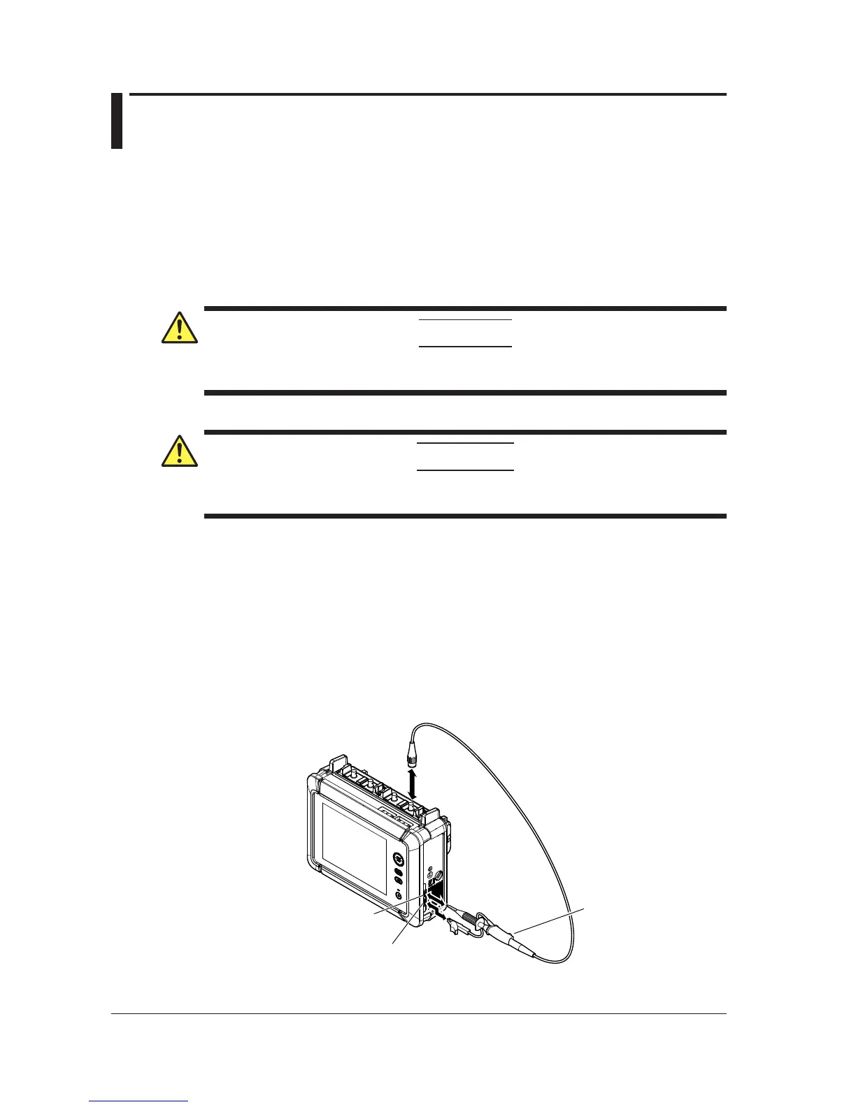
3.
Connect the tip of the probe to the probe compensation signal output terminal on the front panel
of the instrument, and connect the ground wire to the probe compensation signal GND terminal.
4.
Follow the instructions in section 3.6, “Performing Auto Setup,” to perform auto setup on the
probe.
5.
Insert a screwdriver into the phase adjustment hole, and turn the variable capacitor so that the
displayed waveform is an appropriate square wave.
 Loading...