IM 1C22H1-01E
5-2
5. WIRING
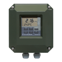
5.3.3 BRAIN TERMINAL BT200 Connec-
tion
Connect the BT200 to the SUPPLY + and – terminals
(Use hooks).
Transmitter terminal box
BT200
F0503.EPS
Power supply
–
+
Ignore the polarity
since the BT200 is
AC-coupled to the
terminal box.
Figure 5.3.3 BT200 Connection
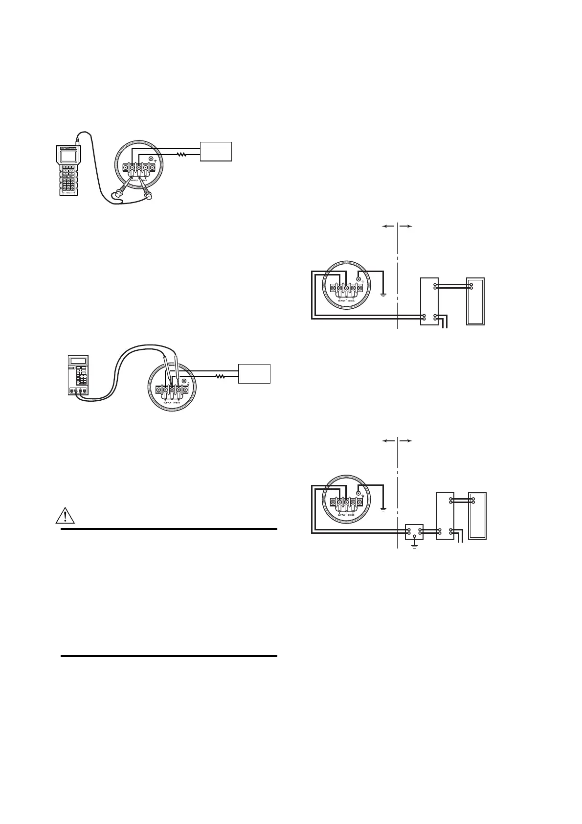
5.3.4 Check Meter Connection
Connect the check meter to the CHECK + and –
terminals (use hooks).
• A 4 to 20 mA DC output signal from the CHECK +
and – terminals.
(Note) Use a check meter whose internal resistance is 10 Ω or less.
Transmitter terminal box
F0504.EPS
Power supply
–
+
Check meter
Figure 5.3.4 Check Meter Connection
5.4 Wiring
CAUTION
For the intrinsically safe equipment and flame-
proof equipment, wiring materials and wiring
work for these equipment including peripherals
are strictly restricted. Users absolutely must read
“Installation and Operating Precautions for JIS
Intrinsically Safe Equipment” and “Installation
and Operating Precautions for JIS Flameproof
Equipment” at the end of this manual prior to the
work.
5.4.1 Loop Configuration
Since the DPharp uses a two-wire transmission system,
signal wiring is also used as power wiring.
DC power is required for the transmitter loop. The
transmitter and distributor are connected as shown
below.
For details of the power supply voltage and load
resistance, see Section 5.6; for communications line
requirements, see Subsection 7.1.2.
(1) General-use Type and Flameproof Type
Hazardous Location Nonhazardous Location
Transmitter terminal box
Distributor
(Power supply unit)
Receiver
instrument
F0505.EPS
Figure 5.4.1a Connection between Transmitter and
Distributor
(2) Intrinsically Safe Type
For intrinsically safe type, a safety barrier must be
included in the loop.
Hazardous Location Nonhazardous Location
Transmitter terminal box
Distributor
(Power supply unit)
Receiver
instrument
Safety barrier
F0506.EPS
Figure 5.4.1b Connection between Transmitter and
Distributor

 Loading...