IM 1C22H1-01E
7-12
7. BRAIN TERMINAL BT200 OPERATION
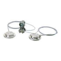
(8) Unit Setup for Displayed Static Pressure
(D31: STAT.P.UNIT)
Follow the procedure below to change the static
pressure units.
Changing this parameter changes the unit for the A30:
STATIC PRESS (static pressure) display.
• Example: Change the static pressure unit from
kgf/cm
2
to MPa.
ESC
SET
C31:STAT.P.UNIT
kgf/cm^2
< MPa >
< mbar >
< bar >
< gf/cm^2 >
Use the or key
to select “MPa.”
Press the key twice to
enter the setting.
F0724.EPS
mmH
2
O
mmAq
mmWG
mmHg
Torr
kPa
MPa
mbar
bar
gf/cm
2
kgf/cm
2
inH
2
O
inHg
ftH
2
O
psi
atm
Pa
hPa
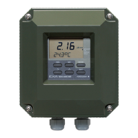
(9) Operation Mode Setup
(D40: REV OUTPUT)
This parameter allows the direction of the 4 to 20 mA
output to be reversed with respect to input. Follow the
procedure below to make this change.
• Example: Change 4 to 20 mA output to 20 to
4 mA output.
ESC
SET
D40:REV OUTPUT
NORMAL
< NORMAL >
< REVERSE>
Use the or key
to select REVERSE.
Press the key twice to
enter the setting.
F0725.EPS
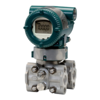
(10) Impulse Line Connection Orientation
Setup (D45: H/L SWAP)
This parameter allows the impulse line connections to
be reversed at the transmitter. Follow the figure below
to make this change.
• Example: Change the impulse line connection
from high pressure on right to high
pressure on left.
ESC
SET
D45:H/L SWAP
NORMAL
< NORMAL >
< REVERSE>
Use the or key
to select REVERSE.
Press the key twice to
enter the setting.
F0726.EPS
(11) Output Status Display/Setup when a CPU
Failure (D52: BURN OUT)
This parameter displays the status of 4 to 20 mA DC
output if a CPU failure occurs. In case of a failure,
communication is disabled.
Setting of HIGH or LOW is enabled. This is done with
the pin (CN4) on the CPU assembly. See Chapter 3 for
details.
Standard specifications
The parameter is set to HIGH. If a failure, the transmit-
ter outputs the signal of 110% or higher. The parameter
D53: ERROR OUT is set to HIGH from the factory.
Optional code/C1
The parameter is set to LOW. If a failure, output which
is –5% or lower is generated. The parameter D53:
ERROR OUT is set to LOW from the factory.
• Example: Standard specifications
pin (CN4) position: H
D52: BURN OUT
HIGH
F0727.EPS
• Example: Optional code/C1
pin (CN4) position: L
D52: BURN OUT
LOW
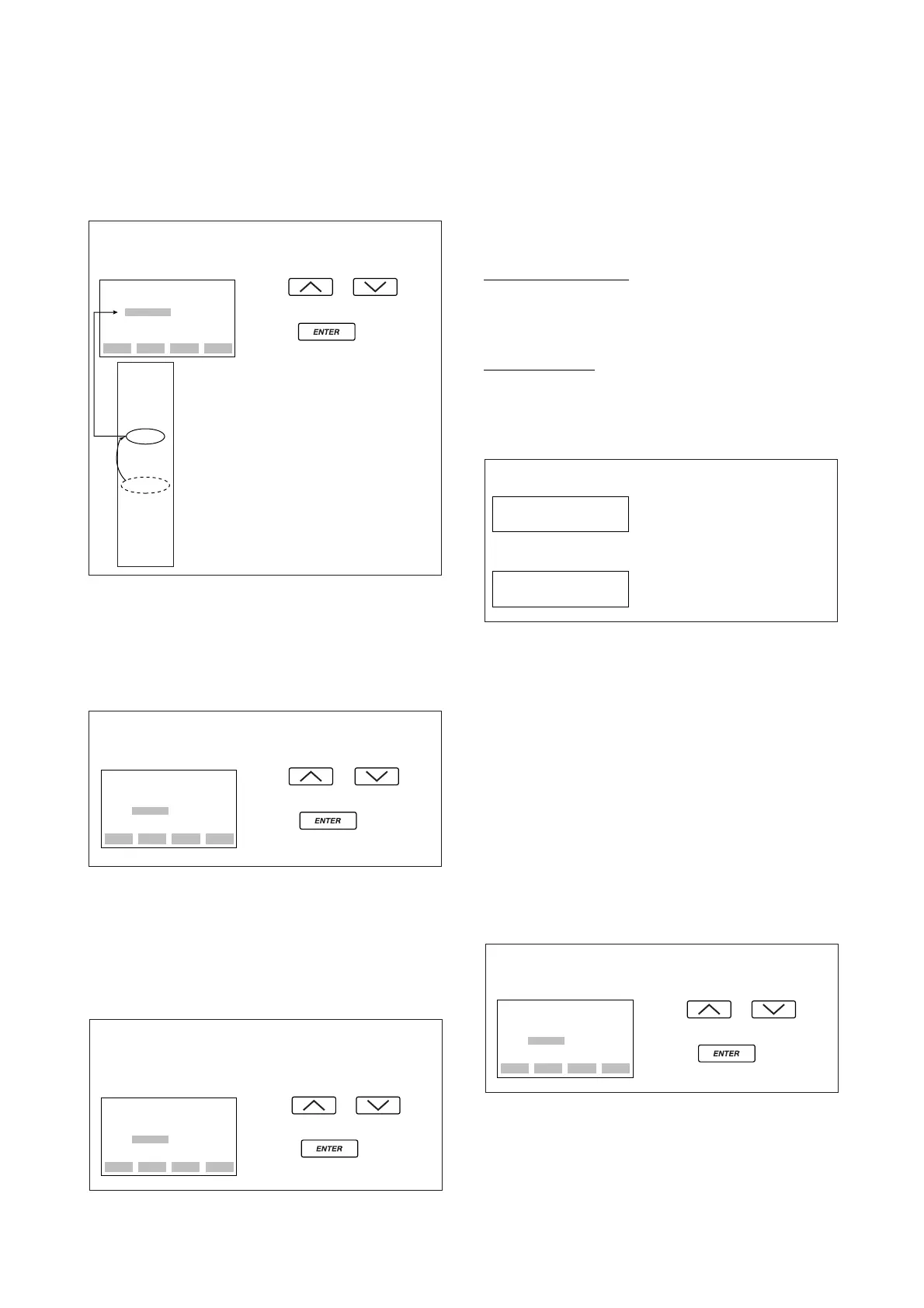
(12) Output Status Setup when a Hardware
Error Occurs (D53: ERROR OUT)
This parameter allows the setting of the output status
when a hardware error occurs. The following three
selections are available.
(a) HOLD; Outputs the last value held before the error
occurred.
(b) HIGH; Outputs an output of 110% when an error
has occurred.
(c) LOW; Outputs an output of –5% when an error has
occurred.
Note: A hardware error means CAP MODULE FAULT of Er.01 or
AMP MODULE FAULT of Er. 02 which are shown in 7.5.2
“Errors and Countermeasures.”)
• Example: Set the output status to LOW when
a hardware error occurs.
ESC
SET
D53:ERROR OUT
HIGH
< HIGH>
< LOW>
< HOLD>
Use the or key
to select “LOW.”
Press the key twice to
enter the setting.
F0728.EPS
 Loading...