IM 1C22H1-01E
6-2
6. OPERATION
6.2 Zero Point Adjustment
Adjust the zero point after operating preparation is
completed.
IMPORTANT
Do not turn off the power to the transmitter
immediately after a zero adjustment. Powering
off within 30 seconds after a zero adjustment will
return the adjustment back to the previous
settings.
The zero point adjustment can be made in either way:
using the zero-adjustment screw of the transmitter or
the BT200 operation.
For output signal checking, display the parameter A10:
OUTPUT (%) in the BT200.
Output signal (%)
display
PARAM
A10:OUTPUT(%)
0.0 %
A11:ENGR OUTPUT
A20:AMP TEMP
DATA DIAG PRNT ESC
F0604.EPS
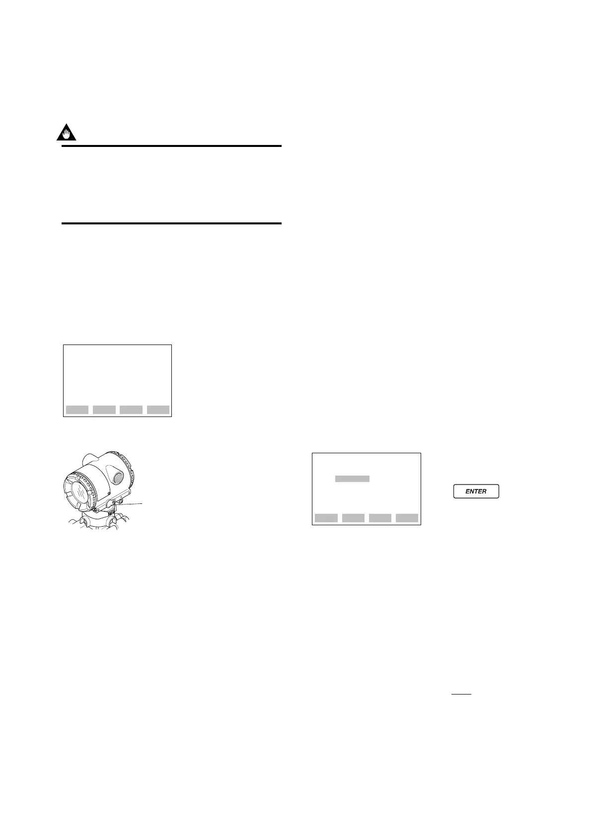
Zero-adjustment
screw
dBT200
dZero-adjustment Screw
When adjusting the transmitter zero point, the liquid
level in a tank does not have to be set to the low limit
(0%) of the measuring range. In such case, match the
transmitter output signal with the actual measured
value using a glass gauge, for example.
6.2.1 When you can obtain Low Range
Value from actual measured value
of 0% (0 kPa, atmospheric pres-
sure);
j Using the Transmitter Zero-adjustment
Screw
Before adjusting a screw, check that the parameter
J20: EXT ZERO ADJ displays ENABLE. See
Subsection 7.3.3 (12) for the setting procedure.
Use a slotted screwdriver to turn the zero-adjustment
screw. Turn the screw clockwise to increase the output
or counterclockwise to decrease the output. The zero
point adjustment can be made with a resolution of
0.01% of the setting range. Since the degree of zero
adjustments varies with the screw turning speed, turn
the screw slowly for fine adjustment and quickly for
coarse adjustment.
j Using the BT200
Zero point can be adjusted by simple key operation of
the BT200.
Select parameter J10: ZERO ADJ, and press the
ENTER key twice. The zero point will be adjusted
automatically to the output signal 0% (4 mA DC).
Confirm that the setting value displayed for the
parameter is ‘0.0%’ before pressing the ENTER key.
See Subsection 7.3.3 (12) for BT200 operating proce-
dures.
A display when parameter
J10 is selected.
Press key
twice for 0% output 4 mA DC.
SET
J10:ZERO ADJ
–0.0 %
+ 000.0
CLR ESC
F0605.EPS
6.2.2 When you cannot obtain Low Range
Value from actual measured value
of 0%;
Convert the actual measured value obtained by a glass
gauge into %.
[Example]
The measuring range of 0 to 2 m and the actual
measured value of 0.8 m.
0.8
2
Actual measured value= x 100=40.0%
 Loading...