IM 1C22H1-01E
8-3
8. MAINTENANCE
8.4 Disassembly and Reassem-
bly
This section describes procedures for disassembly and
reassembly for maintenance and component replace-
ment.
Always turn OFF power and shut off and release
pressures before disassembly. Use proper tools for all
operations. Table 8.4.1 shows the tools required.
Table 8.4.1 Instruments Required for Calibration
Tool RemarksQuantity
Phillips screwdriver
Slotted screwdriver
Allen wrenches
Wrench
Torque wrench
Adjustable wrench
Socket wrench
Socket driver
Tweezers
JIS B4633, No. 2
JIS B4648
One each, nominal 3 and
5 mm Allen wrenches
Width across flats, 17 mm
Width across flats, 16 mm
Width across flats, 5.5 mm
T0802.EPS
1
1
2
1
1
1
1
1
1
CAUTION
Precautions for CENELEC, SAA and JIS
Flameproof Type Transmitters
• Flameproof type transmitters must be, as a
rule, removed to a non-hazardous area for
maintenance and be disassembled and reas-
sembled to the original state.
• Two covers are locked by each of an Allen
head bolt (shrouding bolt) on the flameproof
type transmitters. When a shrouding bolt is
driven clockwise by an Allen wrench, it is going
in and cover lock is released, and then a cover
can be opened.
When a cover is closed it should be locked by
a shrouding bolt without fail. Tighten the
shrouding bolt to a torque of 0.7 N·m.
Shrouding bol
Shrouding bolt
F0802.EP
Figure 8.4.1 Shrouding Bolts
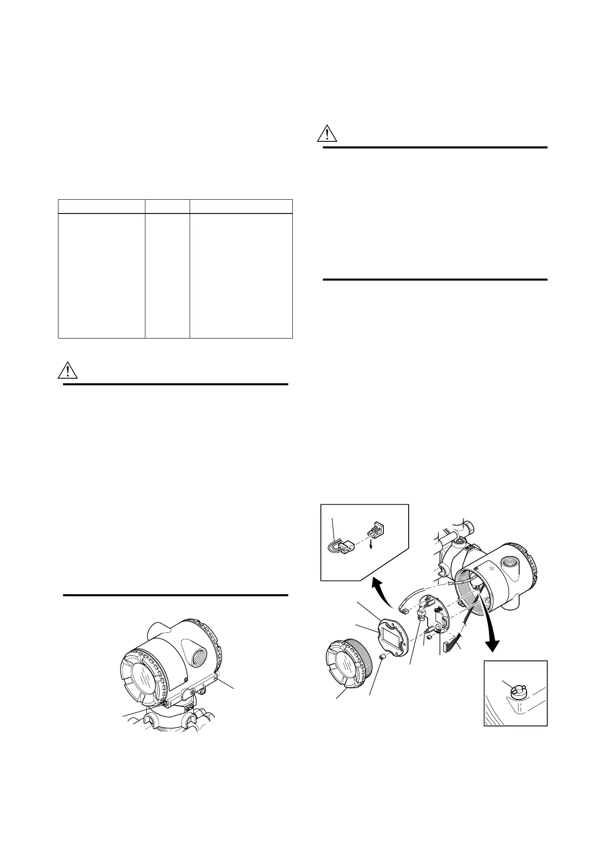
8.4.1 Replacing the Integral Indicator
This subsection describes the procedure for replacing
an integral indicator. (See Figure 8.4.2)
CAUTION
Precautions for JIS Flameproof Type Trans-
mitters
Users are prohibited by law from modifying the
construction of a flameproof type transmitter.
Thus the user is prohibited from using a flame-
proof type transmitter with its integral indicator
removed, or from adding an integral indicator to
a transmitter. If such modification is absolutely
required, contact Yokogawa.
j Removing the Integral Indicator
1) Remove the cover.
2) Supporting the integral indicator by hand, loosen
its two mounting screws.
3) Dismount the LCD board assembly from the CPU
assembly.
When doing this, carefully pull the LCD board
assembly straight forward so as not to damage the
connector between it and the CPU assembly.
j Attaching the Integral Indicator
1) Align both the LCD board assembly and CPU
assembly connectors and engage them.
2) Insert and tighten the two mounting screws.
3) Replace the cover.
F0803.EPS
Press
forward
Output terminal cable
LCD board
assembly
Integral
indicator
Cover
Boss
CPU assembly
Flat cable
Bracket
(for zero-adjustment
screw pin)
Mounting
screw
Zero-adjustment
screw pin
Figure 8.4.2 Removing and Attaching LCD Board
Assembly and CPU Assembly
 Loading...