<3.Installation>
19
IM01C25A01-01E
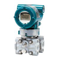
3.2.1 EJ210
Thetransmitterismountedonaprocessusingits
highpressuresideangeasshowninFigure3.5.The
customershouldpreparethematingange,gasket,stud
boltsandnuts.
F0305.ai
Gasket
Stud bolt
Nut
Figure3.5 EJ210Mounting
3.2.2 EJ118andEJ438
Mountthediaphragmsealsusingtheangesasshownin
Figure3.6.Thematingange,gasket,boltsandnutsare
tobeprocuredbythecustomer.
Nut
Flange
Diaphragm
ød
Gasket
F0306.ai
Bolt
The product is
shipped with these
parts assembled.
Correctly install the diaphragm
seals on the high and low pressure
sides of the process (The label on
each diaphragm seal is marked
HIGH or LOW).
Figure3.6 MountingtheDiaphragmSeals
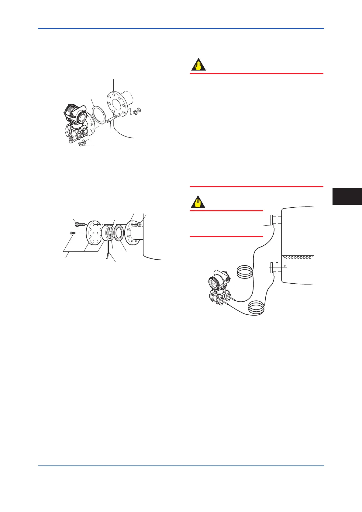
3.3 DiaphragmSealsInstallation
Consideration
IMPORTANT
• Whenmeasuringtheliquidlevelofthetank,the
minimumliquidlevel(zeropoint)mustbesettoa
levelatleast50mmabovethecenterofthehigh
pressuresidediaphragmseal(seeFigure3.7).
• Correctlyinstallthediaphragmsealsonthehigh
andlowpressuresidesoftheprocess,checking
thelabeloneachseal.
• Toavoidmeasuringerrorduetstemperature
differencebetweenthetwodiaphragmseals,
capillarytubemustbeboundtogether.The
capillarytubemustbesecurelyxedtothetank
walltopreventmovementbywindorvibration.
Ifthecapillarytubeistoolong,looselycoilthe
extratubeportion(coildiameterof300mmor
more)andsecurethecoiledtubewithaclamp.
F0307.ai
50 mm minimum
Minimum
liquid level
High
pressure
side
Low
pressure
side
The transmitter should
be installed as low as
possible below the
position where the high
pressure side
diaphragm seal is
installed.
Install the sealed diaphragm
so that the shank positions
downward.
IMPORTANT
Figure3.7 InstallingtheDiaphragmSealstoa
Tank
Installation
3
 Loading...


