<4.InstallingImpulsePiping>
23
IM01C25A01-01E
4. InstallingImpulsePiping
4.1 ImpulsePipingInstallation
Precautions
Theimpulsepipingthatconnectstheprocess
outputstothetransmittermustconveytheprocess
pressureaccurately.If,forexample,gascollectsin
aliquid-lledimpulseline,orthedrainofagas-lled
impulselinebecomesplugged,itwillnotconveythe
pressureaccurately.Sincethiswillcauseerrorsinthe
measurementoutput,selecttheproperpipingmethod
fortheprocessuid(gas,liquid,orsteam).Paycareful
attentiontothefollowingpointswhenroutingtheimpulse
pipingandconnectingtheimpulsepipingtoatransmitter.
4.1.1 ConnectingImpulsePipingtothe
Transmitter
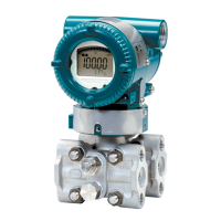
(1) ChecktheHighandLowPressure
ConnectionsontheTransmitter(Figure4.1)
Symbols“H”and“L”havebeenplacedonthecapsule
assemblytoindicatehighandlowpressureside.With
differentialpressuretransmitters,connectthehigh
pressuresideimpulselinetothe“H”side,andthelow
pressuresideimpulselinetothe“L”side.
Withgauge/absolutepressuretransmitters,connectthe
impulselinetothe‘H’side.
F0401.ai
Process
connection
“H” and “L” are shown
Process connection
Process connector
Bolt
Differential Pressure Transmitter
Figure4.1 “H”and“L”SymbolsonaCapsule
Assembly
(2) ChangingtheProcessConnectorPiping
Connections(fordifferentialpressure
transmitters)
Theimpulsepipingconnectiondistancescanbechanged
between51mm,54mmand57mmbychangingthe
orientationoftheprocessconnectors.
Thisisconvenientforaligningtheimpulselinewitha
processconnectors.
57 mm 54 mm 51 mm
F0402.ai
Figure4.2 ProcessConnectorImpulsePiping
ConnectionDistances
(3) TighteningtheProcessConnector
MountingBolts
Afterconnectinganimpulseline,tightentheprocess
connectormountingboltsuniformly.
(4) RemovingtheImpulsePipingConnecting
PortDustproofCap
Theimpulsepipingconnectingportonthetransmitteris
coveredwithaplasticcaptokeepoutdust.Thiscapmust
beremovedbeforeconnectingtheline.(Becarefulnot
todamagethethreadswhenremovingthiscap.Never
insertascrewdriverorothertoolbetweenthecapand
portthreadstoremovethecap.)
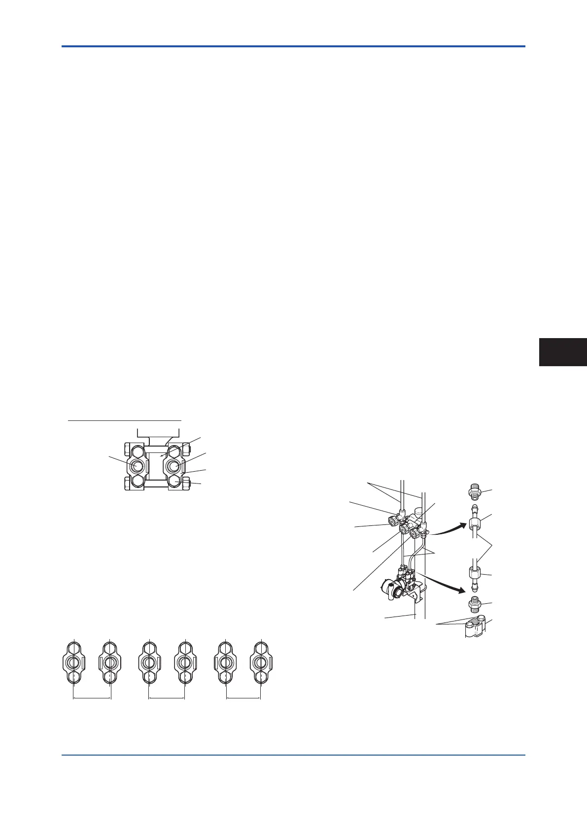
(5) ConnectingtheTransmitterand3-Valve
Manifold(fordifferentialpressure
transmitters)
A3-valvemanifoldconsistsoftwostopvalvestoblock
processpressureandanequalizingvalvetoequalize
thepressuresonthehighandlowpressuresidesofthe
transmitter.Suchamanifoldmakesiteasiertodisconnect
thetransmitterfromtheimpulsepiping,andisconvenient
whenadjustingthetransmitterzeropoint.
Therearetwo3-valvemanifoldtyps:thepipe-mounting
typeandthedirect-mountingtype;careshouldbetaken
withrespecttothefollowingpointswhenconnectingthe
manifoldtothetransmitter.
Pipe-MountingType3-ValveManifold
F0403.ai
Nipple
Nipple
Process
connector
Ball head
lock nut
Pipe
Ball head
lock nut
Process
connector bolts
50 mm(2-inch) pipe
Pipes
3-valve
manifold
Impulse piping
Vent plug
(optional)
Stop valve
(low pressure side)
Equalizing valve
(balancing)
Stop valve
(high pressure side)
Figure4.3 3-ValveManifold(Pipe-MountingType)
InstallingImpulsePiping
4
 Loading...


