<6.Operation>
35
IM01C25A01-01E
6. Operation
NOTE
ForFOUNDATIONFieldbusandPROFIBUSPA
communicationtypesandforthetransmitteroperating
conrmationandzeroingbyanycommunication
method,refertomanualsintheattachedCD-ROMfor
furtherinformation.
6.1 PreparationforStarting
Operation
ConrmingthatTransmitterisOperating
Properly
Ontheintegralindicator
• Ifthewiringsystemisfaulty,thedisplaystaysblank.
• Ifthetransmitterisfaulty,anerrorcodeisdisplayed.
Self-diagnostic error on the integral indicator
(Faulty transmitter)
F0601.ai
NOTE
Ifanyoftheaboveerrorsareindicatedonthedisplay
oftheintegralindicator,refertoChapter7forthe
correctiveaction.
VerifyandChangeTransmitter
ParameterSettingandValues
Theparametersrelatedtothefollowingitemsaresetat
factoryasspeciedinorder.
• Calibrationrange
• Integralindicatordisplay
• Outputmode
• Softwaredamping(optional)
Otherparameterslikefollowingareshippedwiththe
defaultsetting.
• Low-cut
• Processalarmsetting
• Staticpressurerange
• Signalcharacterizer
• Writeprotection
Toconrmorchangethevalues,pleaserefertomanuals
intheattachedCD-ROM.
OutputStatusSettingatCPUFailureand
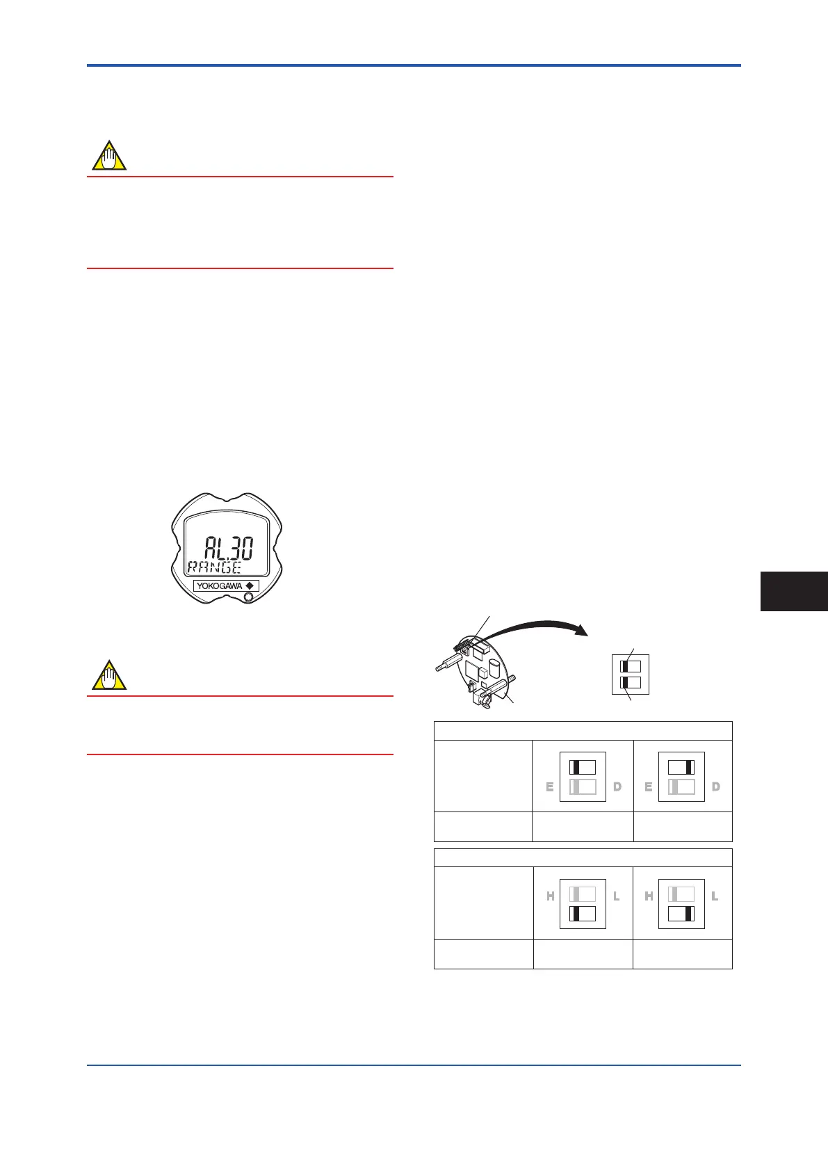
HardwareWriteProtection
Settheswitchesasshowninthegurebelowtosetthe
burn-outdirectionandwriteprotection.TheBurnout
switchissettotheHsidefordelivery(unlessoptioncode
/C1or/C2isspeciedintheorder),andthehardware
writeprotectionswitchissettoEside.Thesettingofthe
switchescanbeconrmedviacommunication.
F0602.ai
H L H L
CPU assembly
BO H L
WR E D
Burnout direction switch
Write protection switch
H L H L
E D E D
Hardware write protection switch (WR)
Write Protection
Switch Position
HIGH LOW
Burnout direction switch (BO)
Burnout Direction
Burnout Direction
Switch Position
YES
(Write disabled)
NO
(Write enabled)
Write Protection
Figure6.1 Burn-outDirectionandHardwareWrite
ProtectionSlideSwitch
Operation
6
 Loading...


