<6.Operation>
36
IM01C25A01-01E
6.2 ZeroPointAdjustment
Aftercompletingpreparationsforoperatingthe
transmitter,adjustthezeropoint.
Zeropointadjustmentcanbedonebyturningthe
transmitter’szero-adjustmentscreworbyusingthe
communicator.Thissectiondescribestheprocedure
forthezero-adjustmentscrew.Forthecommunicator
procedure,pleaserefertomanualsintheattached
CD-ROM.
IMPORTANT
Donotturnoffthepowertothetransmitter
immediatelyafterperformingazeropointadjustment.
Poweringoffwithin30secondsofperformingthis
procedurewillreturnthezeropointtoitsprevious
setting.
6.2.1 AdjustingZeroPointforDifferential
PressureTransmitters
Beforeadjustingzeropoint,makesurethattheequalizing
valveisopen.
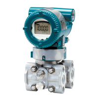
Zero-adjustment screw cover
F0603.ai
Figure6.2 ExternalZeroAdjustmentScrew
Thezero-adjustmentscrewislocatedinsidethecover.
Useaslottedscrewdrivertoturnthezero-adjustment
screw.Equalizethetransmitter,thenturnthescrew
clockwisetoincreasetheoutputorcounterclockwiseto
decreasetheoutput.Thezeropointadjustmentcanbe
madewitharesolutionof0.01%ofthesettingrange.The
degreeofzeroadjustmentsvarieswiththescrewturning
speed;turnthescrewslowlytomakeaneadjustment,
quicklytomakearoughadjustment.
Whenusingdifferentialpressuretransmittersforlevel
measurementandifyoucannotobtainthelowerrange
valuefromtheactualmeasurementvalueof0%,referto
subsection6.2.2(2).
6.2.2 AdjustingZeroPointforGauge/
AbsolutePressureTransmitters
(1) WhenyoucanobtaintheLowRangeValue
fromtheactualmeasuredvalueof0%
(0kPa,atmosphericpressure);
Forpressuremeasurementusinggaugepressure
transmitters,followthestepsbelowbeforeperforming
zeropointadjustment.
1) Closethetapvalve(mainvalve).
2) Loosenthellplugsothatthepressureappliedtothe
transmitterisonlytheheadofthesealliquid.
3) Adjustthezeropointatthisstatus.
4) Aftertheadjustment,closethellplugandthen
graduallyopenthetapvalve.
Useaslottedscrewdrivertoturnthezero-adjustment
screw.Turnthescrewclockwisetoincreasetheoutputor
counterclockwisetodecreasetheoutput.Thezeropoint
adjustmentcanbemadewitharesolutionof0.01%ofthe
settingrange.Sincethedegreeofthezeroadjustment
varieswiththescrewturningspeed,turnthescrewslowly
tomakeaneadjustmentandquicklytomakearough
adjustment.
(2) WhenyoucannotobtaintheLowRange
Valuefromtheactualmeasuredvalueof
0%;
Adjustthetransmitteroutputtotheactualmeasured
valueobtainedbyadigitalmanometeroraglassgauge.
[Example]
Themeasuringrangeof50to250kPa;theactual
measuredvalueof130kPa.
130–50
250–50
Actual measured value=
x100=40.0%
(=10.4mA)
Turnthescrewtomatchtheoutputsignaltotheactual
measuredvalue.
 Loading...


