<5.Wiring>
28
IM01C25A01-01E
5. Wiring
NOTE
ForFOUNDATIONFieldbusandPROFIBUSPA
communicationtypes,pleaserefertomanualsinthe
attachedCD-ROM.
5.1 WiringPrecautions
IMPORTANT
• Laywiringasfaraspossiblefromelectricalnoise
sourcessuchaslargecapacitytransformers,
motors,andpowersupplies.
• Removeelectricalconnectiondustcapbefore
wiring.
• Allthreadedpartsmustbetreatedwith
waterproongsealant.(Anon-hardeningsilicone
groupsealantisrecommended.)
• Topreventnoisepickup,donotpasssignaland
powercablesthroughthesameducts.
• Explosion-protectedinstrumentsmustbewired
inaccordancewithspecicrequirements(and,
incertaincountries,legalregulations)inorder
topreservetheeffectivenessoftheirexplosion-
protectedfeatures.
• TheterminalboxcoverislockedbyanAllenhead
bolt(ashroudingbolt)onATEXameprooftype
transmitters.Whentheshroudingboltisdriven
clockwiseusinganAllenwrench,itgosein.The
coverlockcanthenbereleasedandthecovercan
beopenedbyhand.
Whenacoveriscloseditshouldbelockedbya
shroudingboltwithoutfail.Tightentheshrouding
bolttoatorqueof0.7N·m.
Shrouding Bolt
Shrouding Bolt
F0501.ai
Figure5.1 ShroudingBolt
• Plugandsealanunusedconduitconnection.
5.2 ConnectionsofExternal
WiringtoTerminalBox
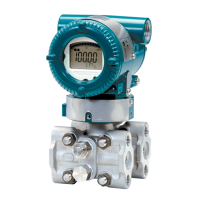
5.2.1 PowerSupplyWiringConnection
ConnectthepowersupplywiringtotheSUPPLY+and
–terminals.
Power supply
–
+
Transmitter terminal box
F0502.ai
SUPPLY
PULSE
CHECK
ALARM
Figure5.2 PowerSupplyWiringConnection
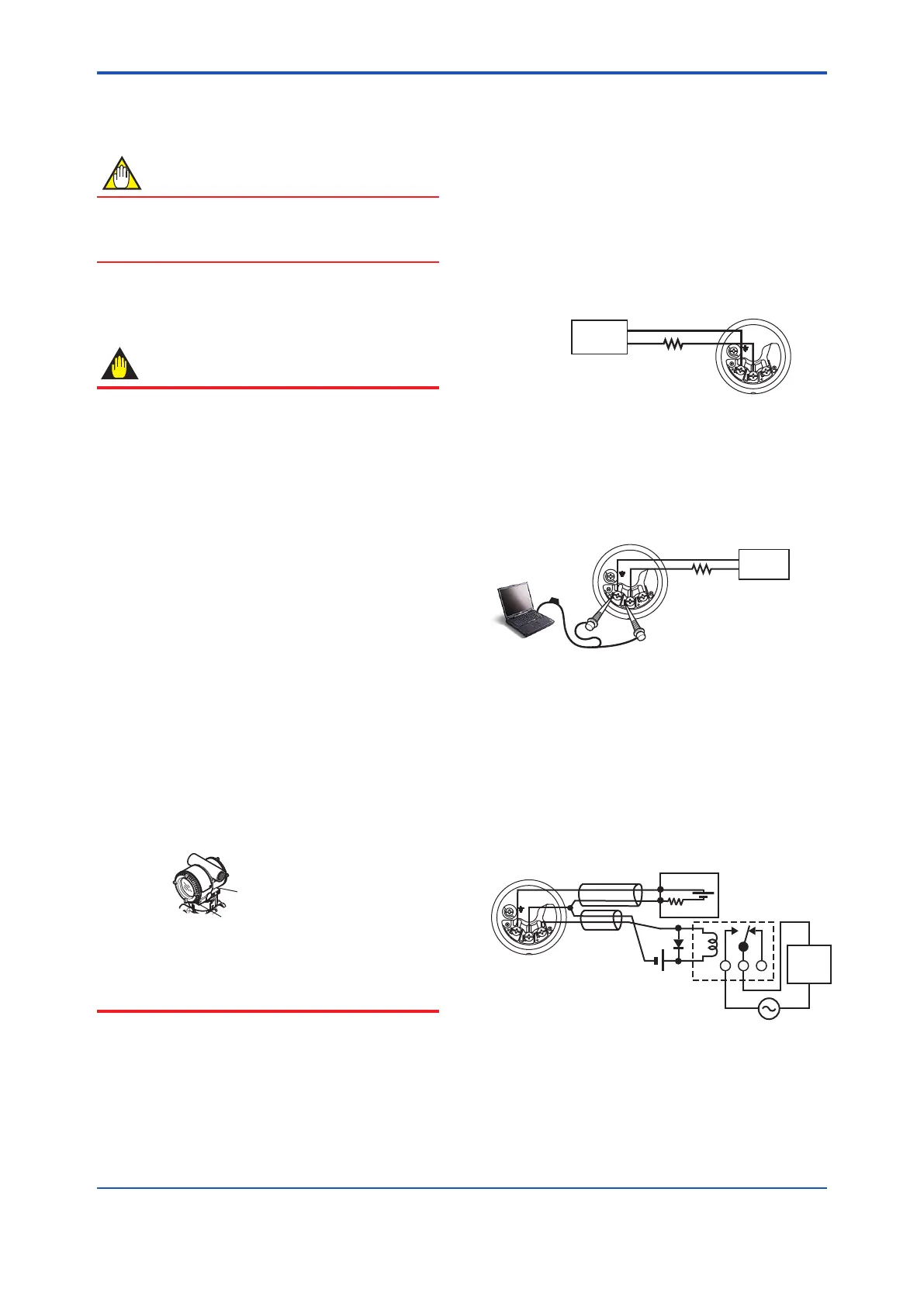
5.2.2 CongurationToolConnection
ConnectthecongurationtooltotheSUPPLY+and
–terminals.(Usehooks.)
SUPPLY
PULSE
CHECK
ALARM
Transmitter terminal box
F0503.ai
Power supply
–
+
Ignore the polarity since
the configuration tool is
AC-coupled to the terminal
box.
USB
FieldMate Modem
PC/FieldMate
Figure5.3 CongurationToolConnection
5.2.3 StatusOutputConnection
Whenoptioncode/ALisspecied,connecttheexternal
wiringasshowninFigure5.4.
Tocongureandactivatetheprocessalarmfunctionand
statusoutput,itisnecessarytosetsomeparameters.
Refertoeachcommunicationmanualforprocedures.
SUPPLY
PULSE
CHECK
ALARM
Transmitter
terminal box
Magnetic
valve
AC power supply
External power
supply 30V DC,
120mA max
+
–
250
Ω
24V DC
Use two-wire separately shielded cables.
Distributor
Shielded cable
F0504.ai
Figure5.4 StatusOutputConnection
 Loading...


