<5.Wiring>
29
IM01C25A01-01E
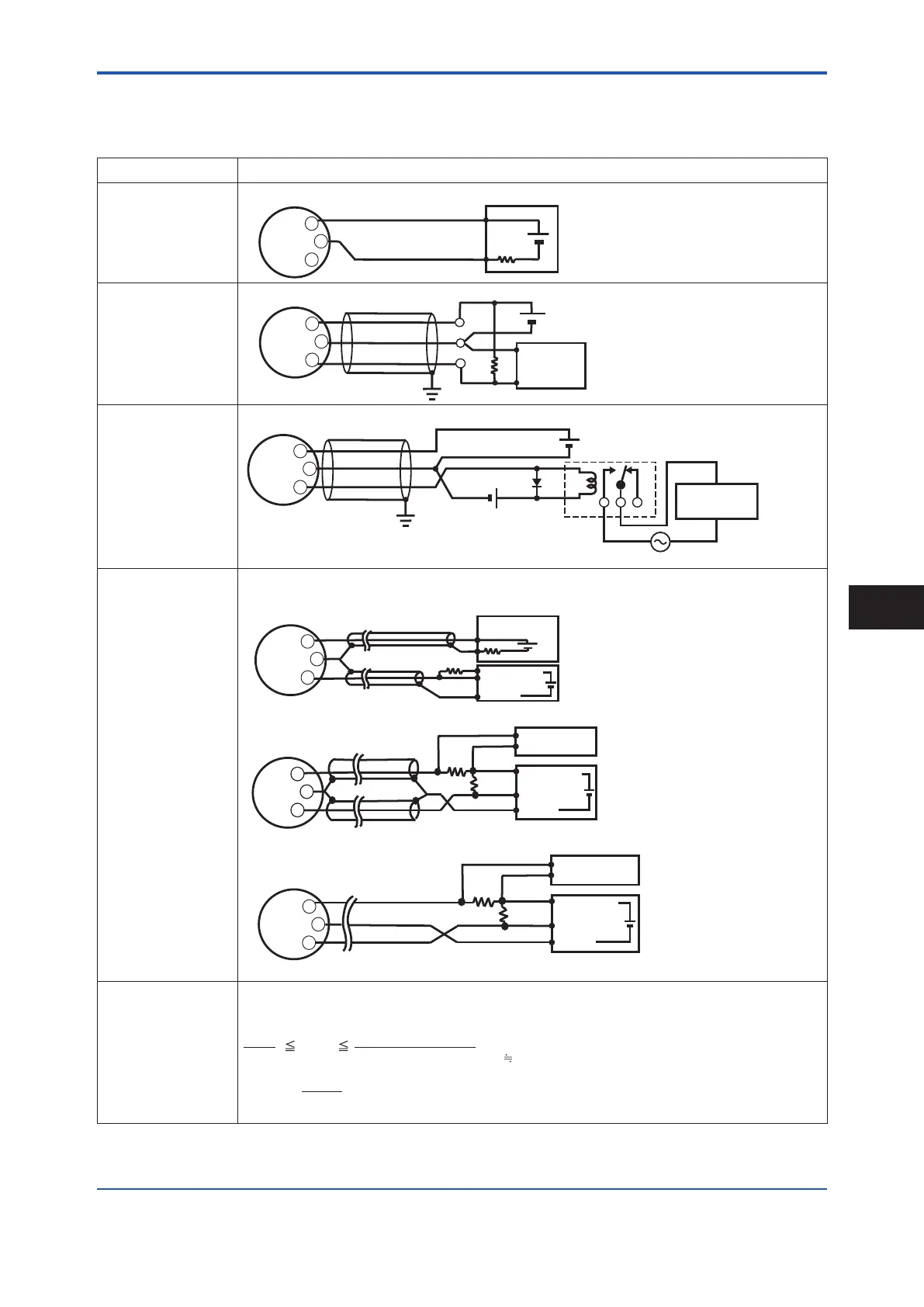
5.2.4 ConnectionExampleforEJX910AandEJX930A
Table5.1 Theconnectionexampleforsimultaneousanalogandpulseandalarm,statusoutput.(ForHART
protocoltype)
OutputType Description
AnalogOutput
Inthiscase,Communication
ispossible(uptoadistance
of2kmwhenaCEVcable
isused.)
Transmitter Electrical Terminal
250Ω
24V DC
+
–
Distributor
PULSE
SUPPLY
+
–
+
PulseOutput
Inthiscase,No
communicationispossible.
R
E
Transmitter Electrical Terminal
Use the Three-wire shielded cable.
Electric counter
*1
*2
Shielded Cable
PULSE
SUPPLY
+
–
+
StatusOutput
Inthiscase,No
communicationispossible.
Use the Three-wire shielded cable.
Shielded Cable
PULSE
SUPPLY
+
–
+
Mognetic
valve
AC power supply
External Power supply
30V DC, 120mA max
(Contact Rating)
Transmitter Electrical Terminal
E
Relay
Simultaneous
Analog
-PulseOutput
*3
Example1
Inthiscase,Communication
ispossible(uptoadistance
of2kmwhenaCEVcable
isused).
Whenanalogandpulseoutputareused,thelengthofcommunicationlineissubjectedtowiringconditions.Refertoexample
1to3.Ifthecommunicationcarriesoutfromamplier,noneedtoconsiderwiringconditions.
*1
*2
250
Ω
R
E(10.5 to 30V DC)
Counting input
Common
24V DC
PULSE
SUPPLY
For the shielded cables in this example of
flowmeter installation, use two-wire separately
shielded cables.
This supply voltage requires a power sourse
with a maximum output current of no less than
E/R.
Distributor (or communication medium : ex. EP card)
(or communication medium : ex. EP card)
Electric counter
+
–
+
Shielded Cable
Transmitter Electrical Terminal
Example2
Inthiscase,Communication
ispossible(uptoadistance
of200mwhenaCEVcable
isused)andR=1kΩ).
*1
*2
250Ω
R
+
–
+
PULSE
SUPPLY
Counting input
Common
For the shielded cables in this
example of flowmeter installation,
use two-wire separately shielded
cables.
This supply voltage requires a power
sourse with a maximum output current
of no less than E/R+25mA.
Recorder or
other instrument
Electric counter
E(16.4 to 30V DC)
Shielded Cable
The supply voltage requires output
impedance no more than 1/1000 of R
(load resistance).
Transmitter Electrical Terminal
Example3
Inthiscase,No
communicationispossible
(whenshieldedcableisnot
used).
250Ω
R
+
–
+
PULSE
SUPPLY
Transmitter Electrical Terminal
Recorder or
other instrument
This supply voltage requires
a power sourse with a
maximum output current of
no less than E/R+25mA.
Electric counter
E(16.4 to 30V DC)
Counting input
Common
*1
*2
Therangeofload
resistanceRforthe
pulseoutput.
Theloadresistanceofpulseoutputshouldbeusedto1kΩ,2W.
Ifnotranslationofthepulseoutputpossiblebythecablelengthorthefrequencyofthepluseoutput,theloadresistance
shouldbeselectedbycalculationasshownbelow.
C ( µF ) × f ( kHz )
R (k
Ω)
120
Example of CEV cable capacitance
0.1µF/km
Where
E = Supply voltage (V)
f = Frequency of pulse output (kHz)
R = Value of load resistance (k
Ω)
C = Cable capacitance (µF)
P = Power ratio of the load resistance
(mW)
P (mW) =
R (k
Ω)
E
2
(V)
*1: Toavoidtheinuenceofexternalnoise,useanelectriccounterwhichtstothepulsefrequency.
*2: Resistorisnotnecessaryincaseofanelectriccounterwhichcanreceivecontactpulsesignaldirectly.
*3: Whenusinganalogandpulseoutputsimultaneously,theHARTcommunicationmaybeinuencedbynoisecomparinganalogoutputonly.Take
countermeasurefornoiseshownabove,e.g.useshieldcableetc.
Wiring
5
 Loading...


