<3.Installation>
22
IM01C25A01-01E
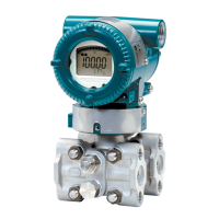
3.6 RotatingTransmitterSection
Thetransmittersectioncanberotatedapproximately
360°(180°toeitherdirectionor360°toonedirection
fromtheoriginalpositionatshipment,dependingonthe
congurationoftheinstrument.)Itcanbexedatany
anglewithinaboverange.
1)Removethetwosetscrewsthatfastenthetransmitter
sectionandcapsuleassembly,usingtheAllen
wrench.
2)Rotatethetransmittersectionslowlyandstopitat
designatedposition.
3)Tightenthetwosetscrewstoatorqueof1.5N·m.
IMPORTANT
Donotrotatethetransmittersectionmorethanthe
abovelimit.
F0312.ai
Vertical impulse piping type
Horizontal impulse piping type
Pressure-detector section
Transmitter section
Rotate 0 to ±180° segments
Rotate 0 to ±180° segments
Transmitter section
Pressure-detector section
Conduit connection
Conduit connection
Zero-adjustment screw
Stopper
Figure3.12 RotatingTransmitterSection
(LeftSideHighPressureType)
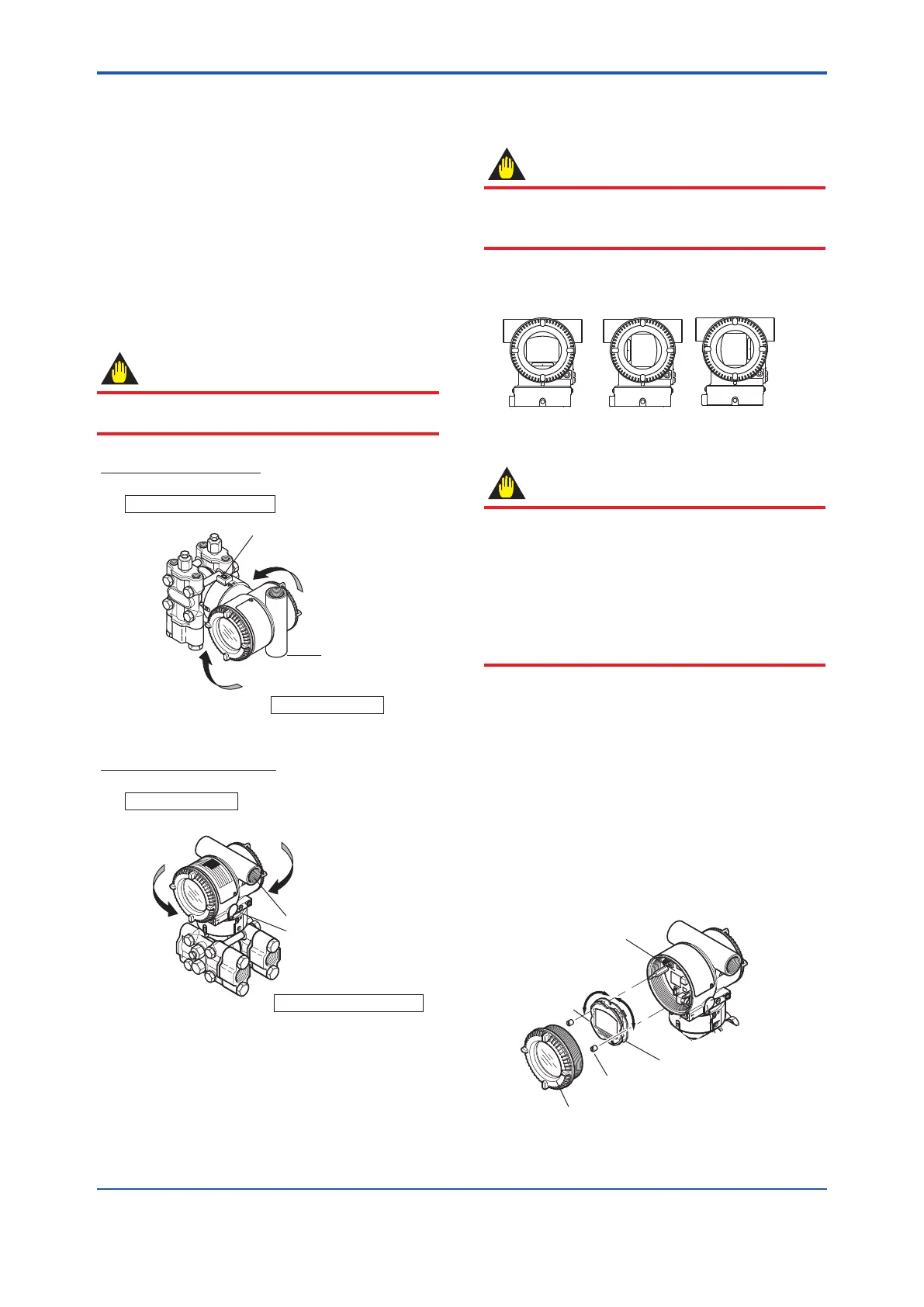
3.7 ChangingtheDirectionof
IntegralIndicator
IMPORTANT
AlwaysturnOFFpower,releasepressureand
removeatransmittertonon-hazardousareabefore
disassemblingandreassmblinganindicator.
Anintegralindicatorcanbeinstalledinthefollowing
threedirections.
F0313.ai
Figure3.13 IntegralIndicatorDirection
IMPORTANT
TheterminalboxcoverislockedbyanAllenhead
bolt(ashroudingbolt)onATEXameprooftype
transmitters.Whentheshroudingboltisdriven
clockwisebyanAllenwrench,itisgoinginandcover
lockisreleased,andthenthecovercanbeopened.
Whenacoveriscloseditshouldbelockedbya
shroudingboltwithoutfail.Tightentheshroudingbolt
toatorqueof0.7N·m.
1) Removethecover.
2) Whilesupportingtheintegralindicatorwithonehand,
loosenitstwomountingscrews.
3) DismounttheLCDboardassemblyfromtheCPU
assembly.Whendoingthis,carefullypulltheLCD
boardassemblystraightforwardsoasnottodamage
theconnectorpinsbetweenitandtheCPUassembly.
4) AfterrotatingtheLCD,alignboththeLCDboard
assemblyandCPUassemblyconnectorsandengage
them.
5) Insertandtightenthetwomountingscrews.
6) Replacethecover.
90°
90°
Integral
indicator
Mounting screw
Amplifier cover
LCD board assembly
CPU assembly
F0314.ai
Figure3.14 RotatingIntegralIndicator
 Loading...


