<4.InstallingImpulsePiping>
24
IM01C25A01-01E
1) Screwnipplesintotheconnectionportsonthe
transmittersideofthe3-valvemanifold,andinto
theimpulsepipingconnectingportsontheprocess
connectors.(Tomaintainpropersealing,windsealing
tapearoundthenipplethreads.)
2) Mountthe3-valvemanifoldonthe50mm(2-inch)
pipebyfasteningaU-bolttoitsmountingbracket.
TightentheU-boltnutsonlylightlyatthistime.
3) Installthepipeassembliesbetweenthe3-valve
manifoldandtheprocessconnectorsandlightly
tightentheballheadlocknuts.(Theball-shapedends
ofthepipesmustbehandledcarefully,sincetheywill
notsealproperlyiftheballsurfaceisscratchedor
otherwisedamaged.)
4) Nowtightenthenutsandboltssecurelyinthe
followingsequence:
Processconnectorbolts→transmitter-endballhead
locknuts→3-valvemanifoldballheadlocknuts→
3-valvemanifoldmountingbracketU-boltnuts
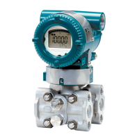
Direct-MountingType3-ValveManifold
1) Mountthe3-valvemanifoldonthetransmitter.(When
mounting,usethetwogasketsandthefourbolts
providedwiththe3-valvemanifold.Tightenthebolts
evenly.)
2) Mounttheprocessconnectorsandgasketsonthetop
ofthe3-valvemanifold(thesideonwhichtheimpulse
pipingwillbeconnected.)
Bolts
Process
connector
Gasket
Gasket
Process
connector
Bolts
Stop valve
Stop valve
3-valve
manifold
3-valve
manifold
Equalizing valve
Equalizing
valve
Stop valve
Impulse
piping
Impulse
piping
Stop valve
F0404.ai
Figure4.4 3-ValveManifold(Direct-MountingType)
NOTE
Aftercompletingtheconnectionofthetransmitterand
3-valvemanifold,besuretoCLOSEthelowpressure
andhighpressurestopvalves,OPENtheequalizing
valve,andleavethemanifoldwiththeequalizingvalve
OPEN.
Youmustdothisinordertoavoidoverloadingthe
transmitterfromeitherthehighorthelowpressure
sidewhenbeginningoperation.
4.1.2 RoutingtheImpulsePiping
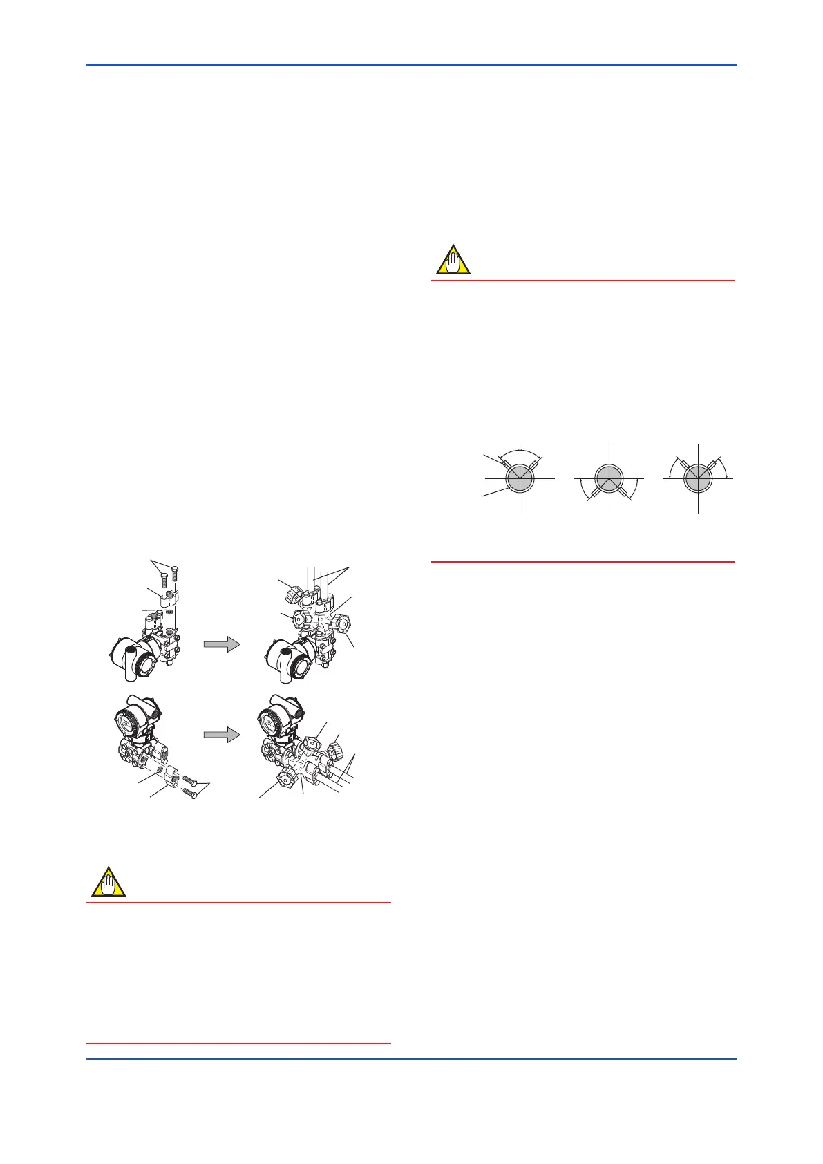
(1) ProcessPressureTapAngles
Ifcondensate,gas,sedimentorotherextraneous
materialintheprocesspipinggetsintotheimpulse
piping,pressuremeasurementerrorsmayresult.To
preventsuchproblems,theprocesspressuretapsmust
beangledasshowninFigure4.5accordingtothekindof
uidbeingmeasured.
NOTE
• Iftheprocessuidisagas,thetapsmustbe
verticalorwithin45°eithersideofvertical.
• Iftheprocessuidisaliquid,thetapsmustbe
horizontalorbelowhorizontal,butnotmorethan
45°belowhorizontal.
• Iftheprocessuidissteamorothercondensing
vapor,thetapsmustbehorizontalorabove
horizontal,butnotmorethan45°abovehorizontal.
[Gas]
Pressure
taps
Process
piping
[Steam][Liquid]
45°
45°
45° 45°
45°
45°
F0405.ai
Figure4.5 ProcessPressureTapAngle
(ForHorizontalPiping)
(2) PositionofProcessPressureTapsand
Transmitter
Ifcondensate(orgas)accumulatesintheimpulsepiping,
itshouldberemovedperiodicallybyopeningthedrain
(orvent)plugs.However,thiswillgenerateatransient
disturbanceinthepressuremeasurement,andtherefore
itisnecessarytopositionthetapsandroutetheimpulse
pipingsothatanyextraneousliquidorgasgeneratedin
theleadlinesreturnsnaturallytotheprocesspiping.
• Iftheprocessuidisagas,thenasarulethe
transmittermustbelocatedhigherthantheprocess
pressuretaps.
• Iftheprocessuidisaliquidorsteam,thenasa
rulethetransmittermustbelocatedlowerthanthe
processpressuretaps.
(3) ImpulsePipingSlope
Theimpulsepipingmustberoutedwithonlyanupwardor
downwardslope.Evenforhorizontalrouting,theimpulse
pipingshouldhaveaslopeofatleast1/10toprevent
condensate(orgases)fromaccumulatinginthepipes.
 Loading...


