1. System Installation Requirements
1-10
TI 32P01J10-01EN
Installation Environment Specications
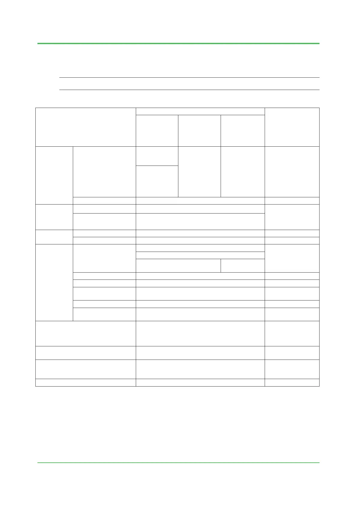
The following table lists environmental requirements for the installation of the ProSafe-RS
System.
SEE
ALSO
For details on each equipment, refer to the ProSafe-RS general specications (GS).
Table Installation Environment Specications (1/2)
Item
Specications
Remarks
Safety Control
Unit (SCU)
Safety Node
Unit, Unit for
Optical Bus
Repeater
Module
N-IO Node
(*1)
Temperature
Normal operation
-20 to 40ºC (*2)
(standard type
SCU for Vnet/IP)
-20 to 70ºC
(*3) (*4)
-40 to 70ºC
(*5) (*6)
-20 to 70ºC (*3)
(wide range
temperature
type SCU for
Vnet/IP)
Transportation/storage –40 to 85°C
Humidity
Normal operation 5 to 95% RH (non-condensing)
5 to 85% RH when
the SRM53D/
SRM54D/SBM54D is
mounted.
Transportation/storage 5 to 95% RH (non-condensing)
Temperature
change
During operation Within ± 10ºC/h
Transportation/storage Within ± 20ºC/h
Power supply
Voltage range
100 to 120 V AC –15%, +10%
220 to 240 V AC –15%, +10%
24 V DC: –10% to +20%
24 V DC: –15%
to +20%
Frequency 50/60 Hz ± 3Hz
Distortion factor 10% or less
Crest factor
100 V system: 118 V or larger
220 V system : 258 V or larger
Momentary failure 20 ms or less (when receiving the rated AC voltage)
DC power supply ripple
rate
1% p-p maximum
Withstanding voltage
1500 V AC for 1 minute
(for 100-120/220-240 V AC)
500 V AC for 1 minute
(for 24 V DC)
Between power &
grounding terminals
Insulation resistance 20 M ohms at 500 V DC
Between power &
grounding terminals
Grounding
Apply the grounding system which is dened by the
rules and standards of the country or the region.
Dust Maximum of 0.3 mg/m
3
Oct. 5, 2018-00
*1: An N-IO node consists of S2NN30D, S2BN1D, S2BN4D, S2BN5D, S2MMM843, S2MDV843, S2KPB10, and S2KLF10.
*2: 0 to 40°C when ALR111-S1, ALR121-S1, or ALE111-S1 is mounted.
*3: 0 to 60°C when ALR111-S1, ALR121-S1, or ALE111-S1 is mounted.
*4: -20 to 50°C when S2LP131-S1 is mounted.
0 to 50°C when S2LP131-S1 and ALR111-S1, ALR121-S1, or ALE111-S1 are mounted.
*5: For S2BN4D and S2BN5D, the ambient temperature must be from -20 to 60°C.
*6: When the S2NN30D Node Interface Unit is used with an optical ESB bus with the following specications at an altitude of 2000 m or higher,
the ambient temperature range is -40 to 60°C.
S2NN30D-01 S2NN30D-02 S2NN30D-10
S2NN30D-11 S2NN30D-12 S2NN30D-20
S2NN30D-21 S2NN30D-22
For cable connector of Base plate with disconnecting terminal (S2BN1D-9), the normal operation temperature is -20 to 70°C as the
temperature specication of the dedicated cable is applied.
 Loading...