1. System Installation Requirements
1-38
TI 32P01J10-01EN
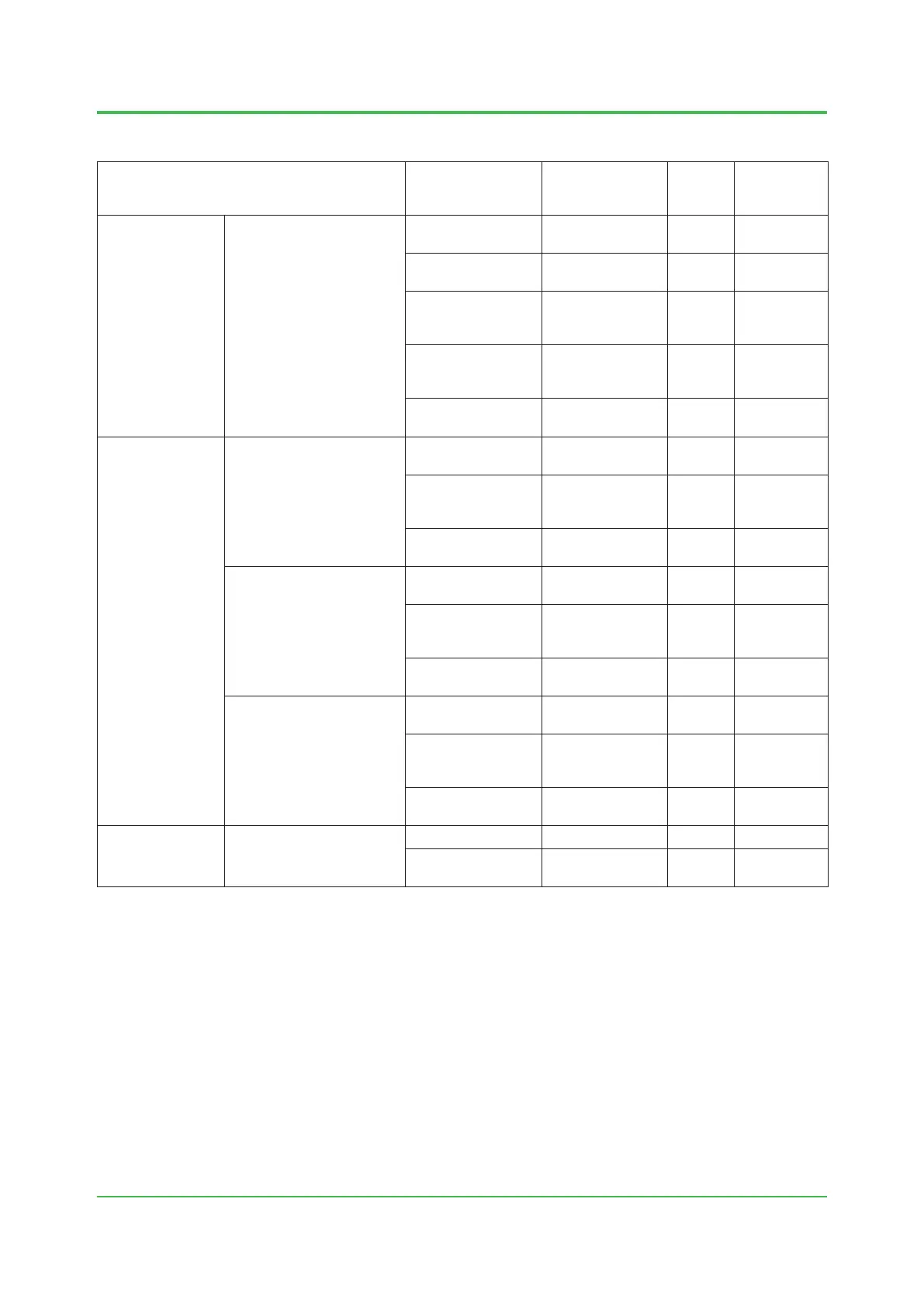
Component Description
Ferrite Core
Model (*1)
Quantity
Location
(See the
Figures)
Node Interface
Unit
S2NN30D N-ESB Bus/Optical
ESB Bus cable
— — —
Power supply input
cable
— — —
System power
supply cable
(S2KLF10)
— — —
System power
supply output cable
(S2KPB10)
— — —
External alarm input
cable
— — —
Base Plate S2BN1D F-SB bus cable
(S2KLF10)
— — —
System power
supply cable
(S2KPB10)
— — —
Field power supply
cable
— — —
S2BN4D F-SB bus cable
(S2KLF10)
— — —
System power
supply cable
(S2KPB10)
— — —
Field power supply
cable
— — —
S2BN5D F-SB bus cable
(S2KLF10)
— — —
System power
supply cable
(S2KPB10)
— — —
Barrier power
cables
— — —
Terminal Boards S1BB4D Power supply cable — — —
Ready contact
cable
— — —
*1: Quantity “—“, Ferrite core is not necessary.
Oct. 25, 2016-00
Table Cables that Need Ferrite Cores to be Attached to, and Ferrite Core Models and Quantities for
Vnet/IP (3/3)
 Loading...